POWER STEERING SYSTEM, Diagnostic DTC:C1521, C1522, C1523, C1524, C1532

| DTC Code | DTC Name |
|---|---|
| C1521 | Motor Circuit Malfunction |
| C1522 | Motor Circuit Malfunction |
| C1523 | Motor Circuit Malfunction |
| C1524 | Motor Circuit Malfunction |
| C1532 | ECU Malfunction |
DESCRIPTION
If the power steering ECU assembly detects these DTCs, it will shut off the motor current sensor, power source relay, motor relay circuit (built into the power steering ECU assembly) and stop power assistance.
| DTC No. | DTC Detection Condition | Trouble Area |
|---|---|---|
| C1521 | Motor overcurrent |
|
| C1522 | Motor current sensor malfunction | |
| C1523 | Excessively large current deviation | |
| C1524 | Voltage error between motor terminals | |
| C1532 | ECU internal malfunction (Peripheral circuit malfunction) is detected |
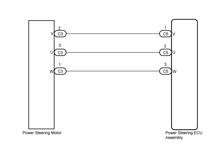
WIRING DIAGRAM
INSPECTION PROCEDURE
PROCEDURE
-
RECONFIRM DTC
-
Check for DTCs Click here.
Result Result Proceed to Only DTC C1521, C1522, C1523, C1524 or C1532 is output A DTC C1555 is output together with other DTCs B Tech Tips
If DTC C1555 is output, perform troubleshooting for C1555 first.
B 
GO TO DIAGNOSTIC TROUBLE CODE CHART Click here
A 
-
-
CHECK CONNECTORS
-
Check the connection of the power steering ECU and rack and pinion power steering gear connectors.
-
Visually inspect the terminals of the power steering ECU and rack and pinion power steering gear connectors.
Result Result Proceed to Normal A Connectors not properly connected B Power steering ECU connector terminals abnormal C Power steering gear connector terminals abnormal D Note
-
If replacing the power steering gear assembly, clear the rotation angle sensor value calibration value, initialize the rotation angle sensor, and calibrate the torque sensor zero point Click here.
-
If replacing the power steering ECU assembly, initialize the rotation angle sensor value and calibrate the torque sensor zero point Click here.
-
B
CONNECT CONNECTORS CORRECTLY
C
REPLACE POWER STEERING ECU ASSEMBLY Click here
D
REPLACE POWER STEERING GEAR ASSEMBLY Click here
A
-
-
CHECK HARNESS AND CONNECTOR (POWER STEERING ECU ASSEMBLY - POWER STEERING MOTOR)
-
Disconnect the C5 connector from the power steering ECU assembly.
-
Disconnect the C3 connector from the power steering motor.
-
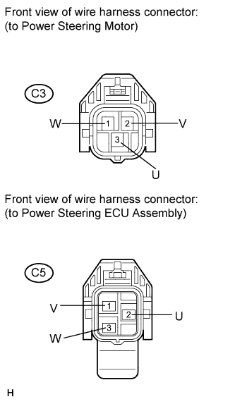
Measure the resistance according to the value(s) in the table below.
Standard Resistance Tester Connection Condition Specified Condition C5-1 (V) - C3-2 (V) Always Below 1 Ω C5-2 (U) - C3-3 (U) Always Below 1 Ω C5-3 (W) - C3-1 (W) Always Below 1 Ω C5-1 (V) - Body ground Always 10 kΩ or higher C5-2 (U) - Body ground Always 10 kΩ or higher C5-3 (W) - Body ground Always 10 kΩ or higher
NG
REPAIR OR REPLACE HARNESS OR CONNECTOR
OK
-
-
INSPECT POWER STEERING GEAR ASSEMBLY (POWER STEERING MOTOR)
-
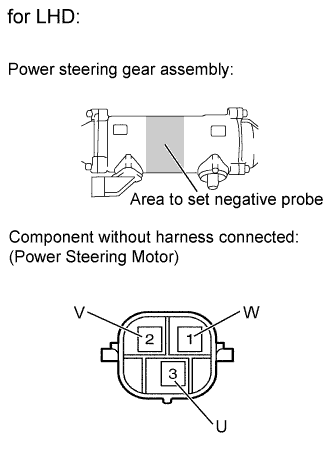
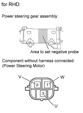
Measure the resistance according to the value(s) in the table below.
Standard Resistance Tester Connection Condition Specified Condition C3-3 (U) - C3-2 (V) Always 0.07 to 10 Ω C3-2 (V) - C3-1 (W) Always 0.07 to 10 Ω C3-1 (W) - C3-3 (U) Always 0.07 to 10 Ω C3-3 (U) - Body ground* Always 100 kΩ or higher C3-2 (V) - Body ground* Always 100 kΩ or higher C3-1 (W) - Body ground* Always 100 kΩ or higher
-
*: Touch the negative probe to the power steering gear assembly housing at the position shown in the illustration to perform the measurement.
Note
-
If replacing the power steering gear assembly, clear the rotation angle sensor value calibration value, initialize the rotation angle sensor, and calibrate the torque sensor zero point Click here.
-
If replacing the power steering ECU assembly, initialize the rotation angle sensor value and calibrate the torque sensor zero point Click here.
-
NG
REPLACE POWER STEERING GEAR ASSEMBLY Click here
OK 
REPLACE POWER STEERING ECU ASSEMBLY Click here
-