PARKING BRAKE ASSEMBLY REASSEMBLY

Tech Tips
When installing the parking brake anchor block sub-assembly, refer to the instructions for Installation of the rear axle carrier sub-assembly Click here.
-
APPLY HIGH TEMPERATURE GREASE
-
Apply a thin layer of high temperature grease to the area where the parking brake plate contacts the parking brake shoe Click here.
-
-
INSTALL PARKING BRAKE SHOE LEVER SUB-ASSEMBLY
-
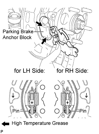
Apply a thin layer of high temperature grease to the area where the parking brake shoe lever contacts the parking brake anchor block.
-
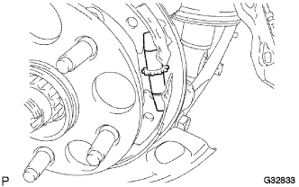
Install the parking brake shoe lever sub-assembly to the parking brake cable assembly.
Note
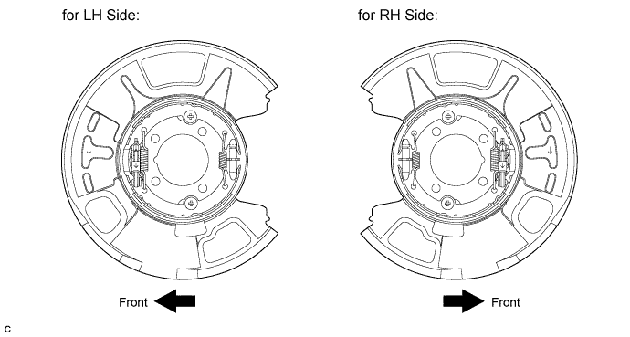
Be sure to install the parking brake shoe lever sub-assembly in the correct position and direction because the direction of the pin is different between the LH side and RH side.
-
-
INSTALL NO. 2 PARKING BRAKE SHOE ASSEMBLY
-
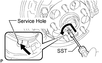
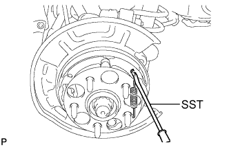
Using SST, install the No. 2 parking brake shoe assembly with the No. 1 shoe hold down spring cup, No. 1 compression spring and No. 1 shoe hold down spring pin.
- SST
- 09718-00011
Tech Tips
Use the service hole to retain the No. 1 shoe hold down spring pin with your finger.
-
-
INSTALL NO. 1 PARKING BRAKE SHOE ASSEMBLY
-
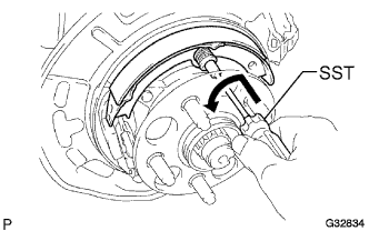
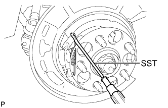
Using SST, install the No. 1 parking brake shoe assembly with the No. 1 shoe hold down spring cup, No. 1 compression spring and No. 1 shoe hold down spring pin.
- SST
- 09718-00011
Tech Tips
Use the service hole to retain the No. 1 shoe hold down spring pin.
-
-
INSTALL PARKING BRAKE SHOE ADJUSTING SCREW SET
-
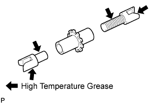
Apply high temperature grease to the threads and all joints of the parking brake shoe adjusting screw set.
-
Install the parking brake shoe adjusting screw set.
-
-
INSTALL NO. 1 PARKING BRAKE SHOE RETURN TENSION SPRING
-
Using SST, install the No. 1 parking brake shoe return tension spring.
- SST
- 09703-30011
-
-
INSTALL NO. 2 PARKING BRAKE SHOE RETURN TENSION SPRING
-
Using SST, install the No. 2 parking brake shoe return spring.
- SST
- 09703-30011
-
-
INSPECT PARKING BRAKE INSTALLATION
-
Make sure that all parts are installed properly. If necessary, reinstall them properly.
-
-
INSTALL REAR DISC
-
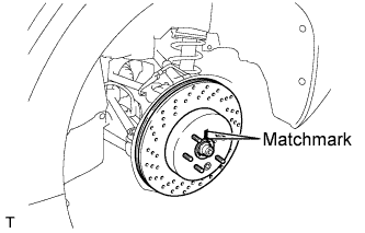
Align matchmarks of the rear disc and rear axle hub, and install the rear disc.
Note
When replacing the disc with a new one, select the installation position where the rear disc has minimal runout.
-
-
INSTALL REAR DISC BRAKE CYLINDER ASSEMBLY
-
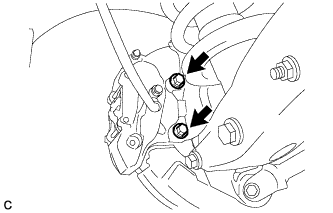
Install the rear disc brake cylinder assembly to the rear axle carrier with the 2 bolts.
- Torque:
- 54 N*m { 551 kgf*cm, 40 ft.*lbf }
Note
-
Do not twist the brake hose.
-
Make sure that the bolts are free from damage and foreign matter.
-
Do not overtighten the bolts.
-
-
INSTALL REAR WHEEL
- Torque:
- 103 N*m { 1050 kgf*cm, 76 ft.*lbf }
-
BED IN PARKING BRAKE SHOES TO DISCS
-
Drive the vehicle at about 50 km/h (31 mph) on a safe, level and dry road.
-
Depress the parking brake pedal with 150 N (15 kgf, 34 lbf) of force.
-
Drive the vehicle for about 400 m (0.25 mile) in this condition.
-
Repeat this procedure 3 times.
Note
Set a 5-minute interval between each procedure to prevent the brake assembly from overheating.
-
-
ADJUST PARKING BRAKE SHOE CLEARANCE AND PARKING BRAKE PEDAL TRAVEL
-
Remove the No. 1 instrument panel under cover sub-assembly Click here.
-
Completely release the parking brake pedal.
-
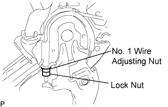
Loosen the lock nut and No. 1 wire adjusting nut to completely release the parking brake cable.
-
Remove the rear wheel.
-
Temporarily install the hub nuts.
-
Remove the shoe adjusting hole plug.
-
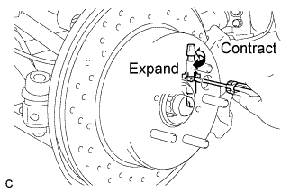
Turn the shoe adjuster and expand the shoe until the disc locks.
-
Turn and contract the shoe adjuster until the disc can rotate smoothly.
Standard Return 7 notches. -
Check that there is no brake drag against the shoe.
-
Install the shoe adjusting hole plug.
-
Turn the adjusting nut until the parking brake pedal travel is corrected to be within the specified range.
Parking brake pedal travel 7 to 9 notches at 300 N (31 kgf, 67.5 lbf) -
Using a wrench or an equivalent tool, hold the adjusting nut and tighten the lock nut.
- Torque:
- 7.0 N*m { 71 kgf*cm, 62 in.*lbf }
-
Operate the parking brake pedal 3 to 4 times, and check the parking brake pedal travel.
-
Check that there is no brake drag against the shoe.
-
Remove the hub nuts.
-
Install the rear wheel.
- Torque:
- 103 N*m { 1050 kgf*cm, 76 ft.*lbf }
-
Install the No. 1 instrument panel under cover sub-assembly Click here.
-
-
INSPECT BRAKE WARNING LIGHT
-
When operating the parking brake pedal, check that the brake warning light illuminates.
Standard The brake warning light always illuminates at the first click.
-