PARKING BRAKE CABLE INSTALLATION

-
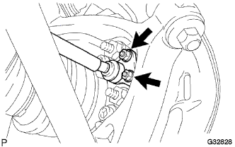
INSTALL CABLE SUPPORT BRACKET
-
Install the cable support bracket with the 2 nuts.
- Torque:
- 76 N*m { 775 kgf*cm, 56 ft.*lbf }
-
-
INSTALL NO. 3 PARKING BRAKE CABLE ASSEMBLY
-
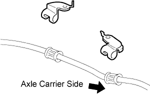
Install the 2 cable support brackets to the No. 3 parking brake cable assembly.
-
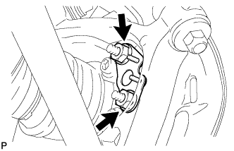
Install the No. 3 parking brake cable assembly to the cable support bracket with the 2 nuts.
- Torque:
- 8.0 N*m { 82 kgf*cm, 71 in.*lbf }
-
Install the No. 3 parking brake cable assembly to the body with the 2 bolts and 2 clamps.
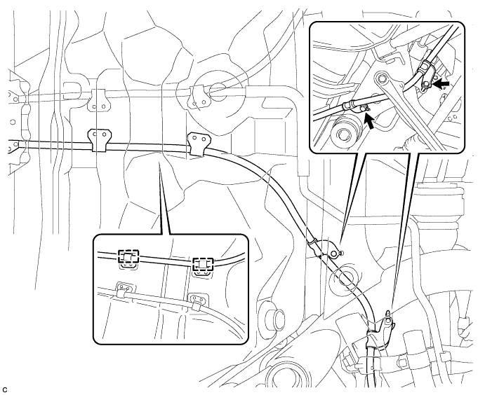
- Torque:
- 19 N*m { 194 kgf*cm, 14 ft.*lbf }
-
-
INSTALL NO. 2 DIFFERENTIAL SUPPORT PROTECTOR
-
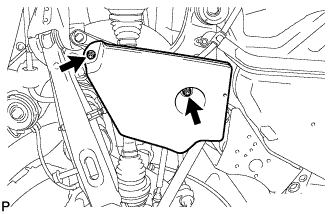
Install the No. 2 differential support protector with the 2 nuts.
-
-
INSTALL NO. 2 PARKING BRAKE CABLE ASSEMBLY
Tech Tips
Use the same procedure for the No. 3 parking brake cable assembly.
-
INSTALL NO. 1 DIFFERENTIAL SUPPORT PROTECTOR
Tech Tips
Perform the same procedure as the No. 2 differential support protector.
-
APPLY HIGH TEMPERATURE GREASE
-
Apply a thin layer of high temperature grease to the area where the parking brake plate contacts the parking brake shoe Click here.
-
-
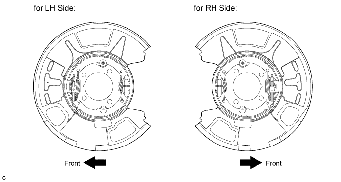
INSTALL PARKING BRAKE SHOE LEVER SUB-ASSEMBLY
-
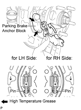
Apply a thin layer of high temperature grease to the area where the parking brake shoe lever contacts the parking brake anchor block.
-
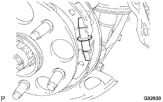
Install the parking brake shoe lever sub-assembly to the parking brake cable assembly.
Note
Be sure to install the parking brake shoe lever sub-assembly in the correct position and direction because the direction of the pin is different between the LH side and RH side.
-
-
INSTALL NO. 2 PARKING BRAKE SHOE ASSEMBLY
-
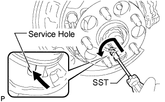
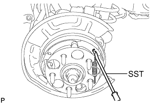
Using SST, install the No. 2 parking brake shoe assembly with the No. 1 shoe hold down spring cup, No. 1 compression spring and No. 1 shoe hold down spring pin.
- SST
- 09718-00011
Tech Tips
Use the service hole to retain the No. 1 shoe hold down spring pin with your finger.
-
-
INSTALL NO. 1 PARKING BRAKE SHOE ASSEMBLY
-
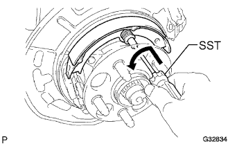
Using SST, install the No. 1 parking brake shoe assembly with the No. 1 shoe hold down spring cup, No. 1 compression spring and No. 1 shoe hold down spring pin.
- SST
- 09718-00011
Tech Tips
Use the service hole to retain the No. 1 shoe hold down spring pin.
-
-
INSTALL PARKING BRAKE SHOE ADJUSTING SCREW SET
-
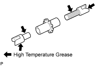
Apply high temperature grease to the threads and all joints of the parking brake shoe adjusting screw set.
-
Install the parking brake shoe adjusting screw set.
-
-
INSTALL NO. 1 PARKING BRAKE SHOE RETURN TENSION SPRING
-
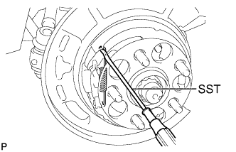
Using SST, install the No. 1 parking brake shoe return tension spring.
- SST
- 09703-30011
-
-
INSTALL NO. 2 PARKING BRAKE SHOE RETURN TENSION SPRING
-
Using SST, install the No. 2 parking brake shoe return spring.
- SST
- 09703-30011
-
-
INSPECT PARKING BRAKE INSTALLATION
-
Make sure that all parts are installed properly. If necessary, reinstall them properly.
-
-
INSTALL REAR DISC
-
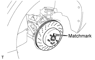
Align matchmarks of the rear disc and rear axle hub, and install the rear disc.
Note
When replacing the disc with a new one, select the installation position where the rear disc has minimal runout.
-
-
INSTALL REAR DISC BRAKE CYLINDER ASSEMBLY
-
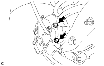
Install the rear disc brake cylinder assembly to the rear axle carrier with the 2 bolts.
- Torque:
- 54 N*m { 551 kgf*cm, 40 ft.*lbf }
Note
-
Do not twist the brake hose.
-
Make sure that the bolts are free from damage and foreign matter.
-
Do not overtighten the bolts.
-
-
INSTALL NO. 1 PARKING BRAKE CABLE ASSEMBLY (for LHD)
-
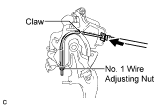
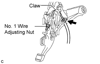
Pass the No. 1 parking brake cable assembly through the parking brake control pedal assembly, and install the clip to the No. 1 parking brake cable assembly.
-
Install the No. 1 wire adjusting nut to the No. 1 parking brake cable assembly.
-
Bend the claw of the parking brake control pedal assembly to hold the No. 1 parking brake cable assembly.
-
-
INSTALL NO. 1 PARKING BRAKE CABLE ASSEMBLY (for RHD)
-
Pass the No. 1 parking brake cable assembly through the parking brake control pedal assembly, and install the clip to the No. 1 parking brake cable assembly.
-
Install the No. 1 wire adjusting nut to the No. 1 parking brake cable assembly.
-
Bend the claw of the parking brake control pedal assembly to hold the No. 1 parking brake cable assembly.
-
-
INSTALL PARKING BRAKE CONTROL PEDAL ASSEMBLY
Tech Tips
Refer to the instructions for Installation of the parking brake control pedal assembly Click here.
-
INSTALL REAR WHEEL
- Torque:
- 103 N*m { 1050 kgf*cm, 76 ft.*lbf }