POWER STEERING SYSTEM DIAGNOSIS SYSTEM

-
DESCRIPTION
-
Connecting the intelligent tester to the vehicle and reading various data output from the power steering ECU assembly is the only difference between usual troubleshooting procedures and those for a vehicle with a diagnostic system.
The power steering ECU assembly records DTCs when the ECU detects a malfunction in the computer itself or in its circuits.
To check the DTCs, connect the intelligent tester to the DLC3. The intelligent tester enables you to clear the DTCs and check the freeze frame data and various forms of steering data.
-
-
CHECK DLC3
-
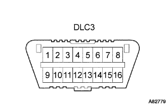
Check the DLC3.
The ECU uses ISO 15765-4 for communication. The terminal arrangement of the DLC3 complies with ISO 15031-3 and matches the ISO 15765-4 format.
Symbol (Terminal No.) Terminal Description Condition Specified Condition SIL (7) - SG (5) Bus "+" line During communication Pulse generation CG (4) - Body ground Chassis ground Always Below 1 Ω SG (5) - Body ground Signal ground Always Below 1 Ω BAT (16) - Body ground Battery positive Always 11 to 14 V CANH (6) - CANL (14) HIGH-level CAN bus line Engine switch off* 54 to 67 Ω CANH (6) - CG (4) HIGH-level CAN bus line Engine switch off* 200 Ω or higher CANL (14) - CG (4) LOW-level CAN bus line Engine switch off* 200 Ω or higher CANH (6) - BAT (16) HIGH-level CAN bus line Engine switch off* 6 kΩ or higher CANL (14) - BAT (16) LOW-level CAN bus line Engine switch off* 6 kΩ or higher Note
*: Before measuring the resistance, leave the vehicle as is for at least 1 minute and do not operate the engine switch, any other switches or the doors.
Tech Tips
Connect the intelligent tester to the DLC3, turn the engine switch on (IG), and attempt to use the intelligent tester. If the screen displays a communication error message, a problem exists on the vehicle side or the intelligent tester side.
-
If communication is normal when connecting the intelligent tester to another vehicle, inspect the DLC3 on the original vehicle.
-
If communication is still not possible when connecting the intelligent tester to another vehicle, the problem is probably in the intelligent tester itself. Consult the Service Department listed in the intelligent tester operator's manual.
-
-
-
P/S WARNING LIGHT
-
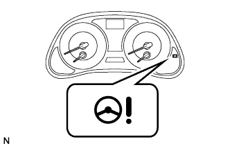
Check that the P/S warning light comes on when the engine switch is turned on (IG) and goes off in approximately 3 seconds.
-
If the warning light does not come on or remains on, inspect the P/S warning light circuit.
Trouble Area See Procedure P/S warning light remains on P/S warning light does not come on
-