REAR BRAKE INSTALLATION

-
INSTALL REAR DISC
-
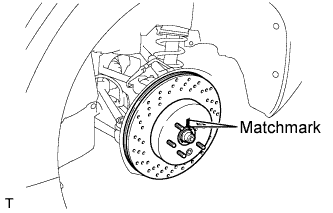
Align matchmarks of the rear disc and rear axle hub, and install the rear disc.
Note
When replacing the disc with a new one, select the installation position where the rear disc has minimal runout.
-
-
INSTALL REAR DISC BRAKE CYLINDER ASSEMBLY
-
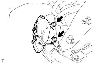
Install the rear disc brake cylinder assembly to the rear axle carrier with the 2 bolts.
- Torque:
- 54 N*m { 551 kgf*cm, 40 ft.*lbf }
-
-
INSTALL REAR DISC BRAKE ANTI-SQUEAL SHIM
-
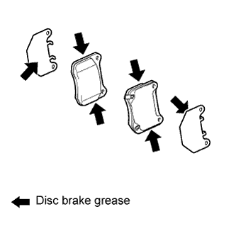
Apply disc brake grease to the rear disc brake anti-squeal shims and rear disc brake pads as shown in the illustration.
Note
When applying the disc brake grease, use the grease enclosed with a rear disc brake pad kit or supplied grease (Part No. 90998-94072) or equivalent.
-
Install the anti-squeal shims to each brake pad.
Note
-
Apply grease to the area that contacts the anti-squeal shims.
-
When replacing worn pads, the anti-squeal shims must be replaced together with the pads.
-
Install the shims in the correct position and direction.
-
The grease can seep out slightly from the area where the anti-squeal shim is installed.
-
There should be no oil or grease on the friction surfaces of the pads and the disc.
-
-
-
INSTALL REAR DISC BRAKE PAD
Note
Be sure to inspect the rear disc when replacing the brake pads with new ones Click here.
-
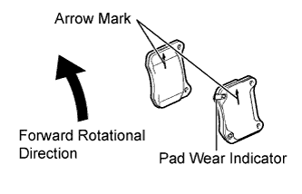
Install the rear disc brake pads to the rear disc brake cylinder assembly.
Note
-
The rear disc brake pad with a pad wear indicator must be installed to the outside position.
-
Match the arrow mark on the rear disc brake pad to the forward rotational direction.
-
-
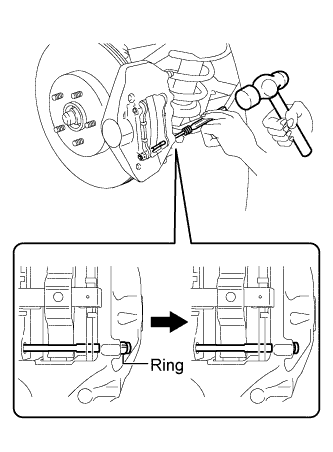
Using a pin punch (5 mm) and a hammer, install the pad guide pin (lower) to the rear disc brake cylinder assembly.
Note
-
Do not damage the disc brake cylinder surface.
-
Securely engage the ring of the pad guide pin (lower) to the rear disc brake cylinder assembly.
-
-
Install the anti-rattle spring to the rear disc brake cylinder assembly.
Note
Securely install the anti-rattle spring in the correct position and direction.
-
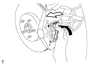
Holding the anti-rattle spring, insert the pad guide pin (upper) to the rear disc brake cylinder assembly.
-
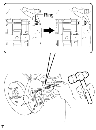
Using a pin punch (5 mm) and a hammer, install the pad guide pin (upper) to the rear disc brake cylinder assembly.
Note
-
Do not damage the disc brake cylinder surface.
-
Securely engage the ring of the pad guide pin to the rear disc brake cylinder assembly.
-
-
-
CONNECT REAR FLEXIBLE HOSE
-
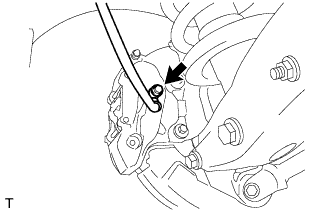
Connect the rear flexible hose to the rear disc brake cylinder assembly with a new union bolt and a new gasket.
- Torque:
- 39 N*m { 398 kgf*cm, 29 ft.*lbf }
Note
Install the flexible hose lock securely in the lock hole in the rear disc brake cylinder assembly.
-
-
FILL RESERVOIR WITH BRAKE FLUID
-
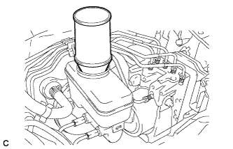
Fill the reservoir with brake fluid.
Brake Fluid SAE J1703 or FMVSS No. 116 DOT 3 Note
Make sure that there is sufficient brake fluid in the reservoir.
-
-
BLEED BRAKE LINE
Note
-
Bleed the brake line of the wheel farthest from the master cylinder first.
-
Add brake fluid to keep the level between the MIN and MAX lines of the reservoir while bleeding the brakes.
-
Depress the brake pedal several times, and then loosen the bleeder plug with the pedal depressed *1.
-
When fluid stops coming out, tighten the bleeder plug, and then release the brake pedal *2.
-
Repeat *1 and *2 until all the air in the fluid is completely bled out.
-
Tighten the bleeder plug completely.
- Torque:
- 19 N*m { 194 kgf*cm, 14 ft.*lbf }
-
Repeat the above procedure for each wheel to bleed the brake line.
-
-
INSPECT FOR BRAKE FLUID LEAK
-
INSPECT BRAKE FLUID LEVEL
-
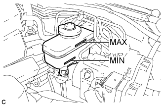
Check the fluid level.
If the brake fluid level is lower than the MIN line, check for leaks and inspect the disc brake pads. If necessary, refill the reservoir with brake fluid after repair or replacement.
Brake Fluid SAE J1703 or FMVSS No. 116 DOT 3
-
-
ADJUST PARKING BRAKE SHOE CLEARANCE AND PARKING BRAKE PEDAL TRAVEL
-
Remove the No. 1 instrument panel under cover sub-assembly Click here.
-
Completely release the parking brake pedal.
-
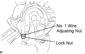
Loosen the lock nut and No. 1 wire adjusting nut to completely release the parking brake cable.
-
Remove the rear wheel.
-
Temporarily install the hub nuts.
-
Remove the shoe adjusting hole plug.
-
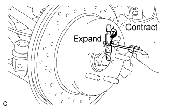
Turn the shoe adjuster and expand the shoe until the disc locks.
-
Turn and contract the shoe adjuster until the disc can rotate smoothly.
Standard Return 7 notches. -
Check that there is no brake drag against the shoe.
-
Install the shoe adjusting hole plug.
-
Turn the adjusting nut until the parking brake pedal travel is corrected to be within the specified range.
Parking brake pedal travel 7 to 9 notches at 300 N (31 kgf, 67.5 lbf) -
Using a wrench or an equivalent tool, hold the adjusting nut and tighten the lock nut.
- Torque:
- 7.0 N*m { 71 kgf*cm, 62 in.*lbf }
-
Operate the parking brake pedal 3 to 4 times, and check the parking brake pedal travel.
-
Check that there is no brake drag against the shoe.
-
Remove the hub nuts.
-
Install the rear wheel.
- Torque:
- 103 N*m { 1050 kgf*cm, 76 ft.*lbf }
-
Install the No. 1 instrument panel under cover sub-assembly Click here.
-
-
INSTALL REAR WHEEL
- Torque:
- 103 N*m { 1050 kgf*cm, 76 ft.*lbf }