BRAKE BOOSTER INSTALLATION

-
INSTALL BRAKE MASTER CYLINDER PUSH ROD CLEVIS
-
Temporarily install the brake master cylinder push rod clevis and lock nut.
Tech Tips
Fully tighten the lock nut after adjusting the brake pedal height Click here.
-
-
INSTALL CHECK VALVE GROMMET
-
Install the check valve grommet to the brake booster assembly.
-
-
INSTALL BRAKE VACUUM CHECK VALVE ASSEMBLY
-
Install the brake vacuum check valve assembly to the brake booster assembly.
-
-
INSTALL BRAKE BOOSTER GASKET
-
Install a new brake booster gasket to the brake booster assembly.
-
-
INSTALL BRAKE BOOSTER ASSEMBLY
-
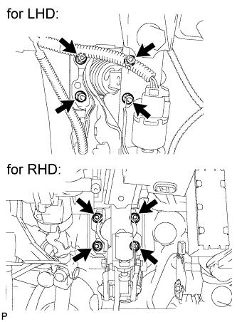
Install the brake booster assembly with the 4 nuts.
- Torque:
- 13 N*m { 133 kgf*cm, 10 ft.*lbf }
Note
Do not damage the brake lines.
-
-
INSTALL BRAKE LINE (for RHD)
-
Engage the clamp to install the 2 brake lines.
Note
Do not damage the brake lines or clamp. If any parts are damaged, replace them with new ones.
-
-
CONNECT VACUUM HOSE (for LHD)
-
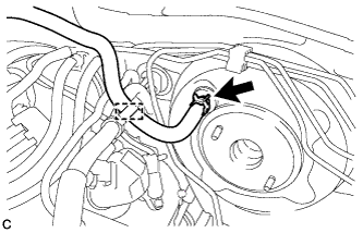
Connect the vacuum hose to the brake vacuum check valve assembly and slide the clip.
-
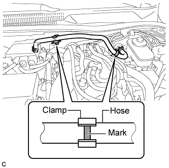
Engage the clamp and inspect the condition of the vacuum hose.
Note
Align the vacuum hose matchmarks and the hose clamp as shown in the illustration.
-
-
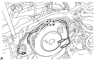
CONNECT VACUUM HOSE (for RHD)
-
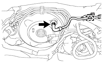
Connect the vacuum hose to the brake vacuum check valve assembly and slide the clip.
-
Engage the clamp and inspect the condition of the vacuum tube.
-
-
CONNECT BRAKE MASTER CYLINDER PUSH ROD CLEVIS
-
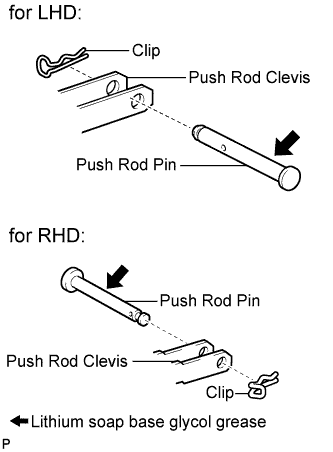
Apply lithium soap base glycol grease to the push rod pin.
-
Connect the brake master cylinder push rod clevis to the brake pedal support assembly with the push rod pin and a new clip.
-
-
INSTALL BRAKE PEDAL RETURN SPRING
-
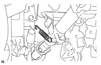
Install the brake pedal return spring.
-
-
CONNECT CABLE TO NEGATIVE BATTERY TERMINAL
-
INSTALL BRAKE MASTER CYLINDER SUB-ASSEMBLY
Tech Tips
Refer to the instructions for Installation of the brake master cylinder sub-assembly Click here.
-
INSPECT AND ADJUST BRAKE PEDAL HEIGHT
-
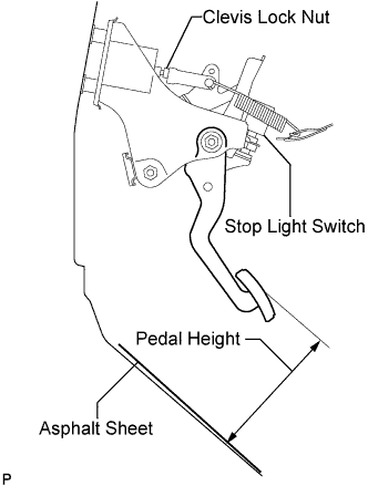
Check the brake pedal height.
Pedal Height from Asphalt Sheet Model Specified Condition LHD 151.8 to 161.8 mm (5.98 to 6.37 in.) RHD 147.0 to 157.0 mm (5.79 to 6.18 in.) -
Adjust brake pedal height.
-
Remove the stop light switch assembly Click here.
-
Loosen the push rod lock nut, and adjust the brake pedal height by turning the push rod.
-
Tighten the push rod lock nut.
- Torque:
- 26 N*m { 265 kgf*cm, 19 ft.*lbf }
-
Install the stop light switch assembly Click here.
-
-
-
INSPECT BRAKE PEDAL FREE PLAY
-
Stop the engine and depress the brake pedal several times until no vacuum is left in the booster.
-
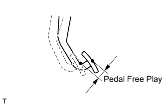
Press the pedal until a slight resistance is felt. Measure the distance as shown in the illustration.
Pedal free play 1.0 to 2.0 mm (0.0394 to 0.0787 in.) If the pedal free play is not as specified, check the stop light switch clearance Click here.
If the stop light switch clearance is within the specified range, it is normal though brake pedal free play is not as specified.
-
-
INSPECT BRAKE PEDAL RESERVE DISTANCE
Tech Tips
Measure the distance at the same point used for the brake pedal height inspection.
-
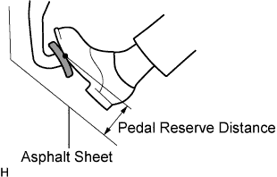
Release the parking brake pedal.
-
With the engine running, depress the pedal and measure the pedal reserve distance as shown in the illustration.
Pedal reserve distance from asphalt sheet at 490 N (50 kgf, 110 lbf) More than 110 mm (4.33 in.) If incorrect, troubleshoot the brake system Click here.
-
-
DISCONNECT CABLE FROM NEGATIVE BATTERY TERMINAL
-
INSTALL DRIVER SIDE KNEE AIRBAG ASSEMBLY
-
Check that the engine switch is off.
-
Check that the battery negative (-) cable is disconnected.
CAUTION:
Wait at least 90 seconds after disconnecting the cable from the negative (-) battery terminal to disable the SRS system.
-
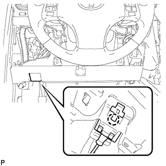
Connect the driver side knee airbag connector to the driver side knee airbag assembly.
Note
When connecting the airbag connector, take care not to damage the airbag wire harness.
-
Temporarily install the driver side knee airbag assembly with the 2 pins.
-
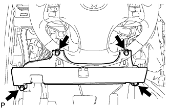
Install the driver side knee airbag assembly with the 4 bolts.
- Torque:
- 10 N*m { 102 kgf*cm, 7 ft.*lbf }
-
Install the hood lock control cable with the claw.
-
-
INSTALL LOWER INSTRUMENT PANEL FINISH PANEL SUB-ASSEMBLY
-
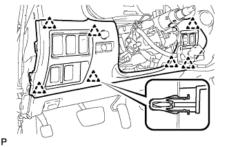
Connect the connectors.
-
Engage the 7 clips and install the lower instrument panel finish panel sub-assembly.
-
-
INSTALL NO. 1 INSTRUMENT PANEL UNDER COVER SUB-ASSEMBLY
-
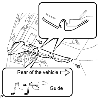
Connect the connectors.
-
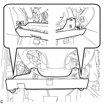
Insert the No. 1 instrument panel under cover sub-assembly into the guide as shown in the illustration.
-
Engage the 2 claws.
-
Install the No. 1 instrument panel under cover sub-assembly with the 2 screws <D>.
-
-
INSTALL SIDE INSTRUMENT PANEL LH (for LHD)
-
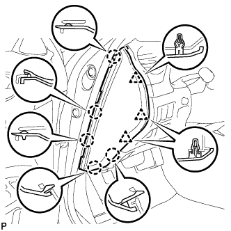
Engage the 5 claws and 3 clips, and then install the side instrument panel LH.
-
-
INSTALL SIDE INSTRUMENT PANEL RH (for RHD)
-
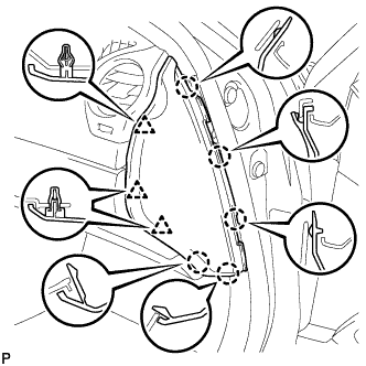
Engage the 5 claws and 3 clips, and then install the side instrument panel RH.
-
-
INSTALL FRONT DOOR OPENING TRIM COVER LH (for LHD)
-
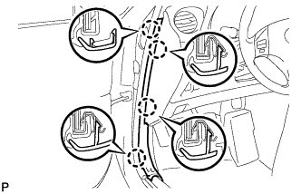
Engage the 4 claws and install the front door opening trim cover LH.
-
-
INSTALL FRONT DOOR OPENING TRIM COVER RH (for RHD)
Tech Tips
Use the same procedure for the RH side and LH side Click here.
-
INSTALL FRONT DOOR SCUFF PLATE LH (for LHD)
-
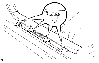
Engage the 4 clips.
-
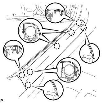
Engage the 7 claws and install the front door scuff plate LH.
-
-
INSTALL FRONT DOOR SCUFF PLATE RH (for RHD)
Tech Tips
Use the same procedure for the RH side and LH side Click here.
-
CONNECT CABLE TO NEGATIVE BATTERY TERMINAL
Note
When disconnecting the cable, some systems need to be initialized after the cable is reconnected Click here.