BRAKE BOOSTER REMOVAL

-
REMOVE BRAKE MASTER CYLINDER SUB-ASSEMBLY
Tech Tips
Refer to the instructions for Removal of the brake master cylinder sub-assembly Click here.
-
DISCONNECT VACUUM HOSE (for LHD)
-
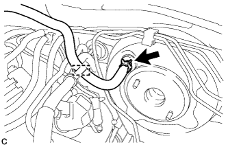
Disengage the clamp.
-
Slide the clip and disconnect the vacuum hose.
-
-
DISCONNECT VACUUM HOSE (for RHD)
-
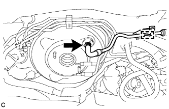
Disengage the clamp.
-
Slide the clip and disconnect the vacuum hose.
-
-
REMOVE BRAKE LINE (for RHD)
-
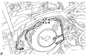
Disengage the clamp and remove the 2 brake lines.
Note
Be careful not to damage the brake lines or clamp. If any parts are damaged, replace them with new ones.
-
-
DISCONNECT CABLE FROM NEGATIVE BATTERY TERMINAL
CAUTION:
Wait at least 90 seconds after disconnecting the cable from the negative (-) battery terminal to disable the SRS system.
-
REMOVE FRONT DOOR SCUFF PLATE LH (for LHD)
-
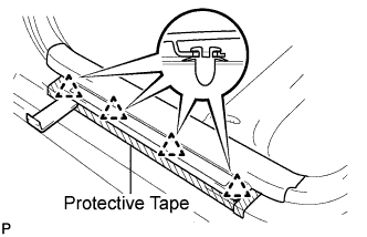
Put protective tape around the front door scuff plate.
-
Using a moulding remover, disengage the 4 clips.
-
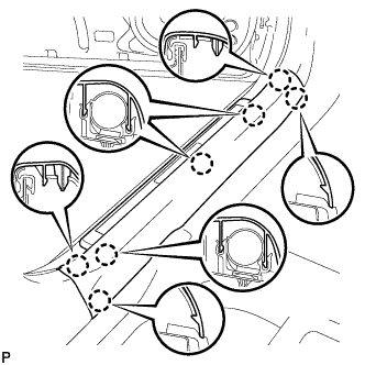
Disengage the 7 claws and remove the front door scuff plate LH.
-
-
REMOVE FRONT DOOR SCUFF PLATE RH (for RHD)
Tech Tips
Use the same procedure for the RH side and LH side Click here.
-
REMOVE FRONT DOOR OPENING TRIM COVER LH (for LHD)
-
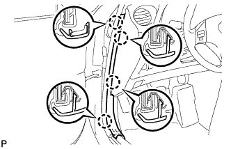
Disengage the 4 claws and remove the front door opening trim cover LH.
-
-
REMOVE FRONT DOOR OPENING TRIM COVER RH (for RHD)
Tech Tips
Use the same procedure for the RH side and LH side Click here.
-
REMOVE SIDE INSTRUMENT PANEL LH (for LHD)
-
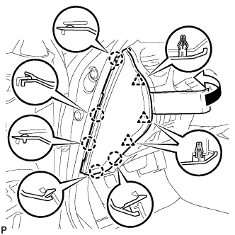
Using a moulding remover, disengage the 5 claws and 3 clips, and then remove the side instrument panel LH.
-
-
REMOVE SIDE INSTRUMENT PANEL RH (for RHD)
-
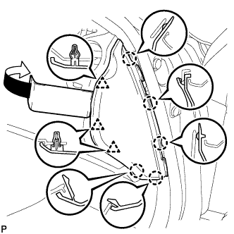
Using a moulding remover, disengage the 5 claws and 3 clips, and then remove the side instrument panel RH.
-
-
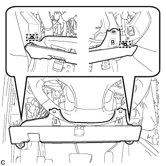
REMOVE NO. 1 INSTRUMENT PANEL UNDER COVER SUB-ASSEMBLY
-
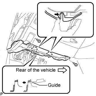
Remove the 2 screws <D>.
-
Push the 2 claws in the direction indicated by the arrow to disengage them.
-
Remove the No. 1 instrument panel under cover sub-assembly from the guide as shown in the illustration and pull the cover toward the rear of the vehicle.
-
Disconnect the connectors and remove the No. 1 instrument panel under cover sub-assembly.
-
-
REMOVE LOWER INSTRUMENT PANEL FINISH PANEL SUB-ASSEMBLY
-
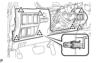
Disengage the 7 clips.
-
Disconnect the connectors and remove the lower instrument panel finish panel sub-assembly.
-
-
REMOVE DRIVER SIDE KNEE AIRBAG ASSEMBLY
-
Check that the engine switch is off.
-
Check that the cable is disconnected from the negative (-) battery terminal.
CAUTION:
Wait at least 90 seconds after disconnecting the cable from the negative (-) battery terminal to disable the SRS system.
-
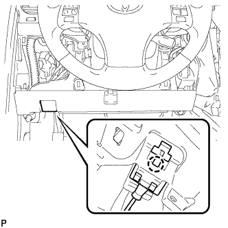
Disengage the claw and separate the hood lock control cable.
-
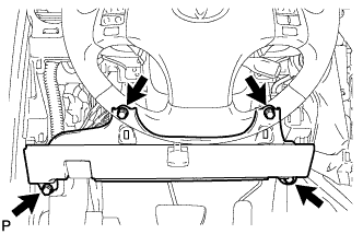
Remove the 4 bolts.
-
Disengage the 2 pins and separate the driver side knee airbag assembly.
-
Disconnect the connector and remove the driver side knee airbag assembly.
Note
When disconnecting the airbag connector, take care not to damage the airbag wire harness.
-
-
REMOVE BRAKE PEDAL RETURN SPRING
-
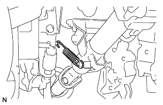
Remove the brake pedal return spring.
-
-
SEPARATE BRAKE MASTER CYLINDER PUSH ROD CLEVIS
-
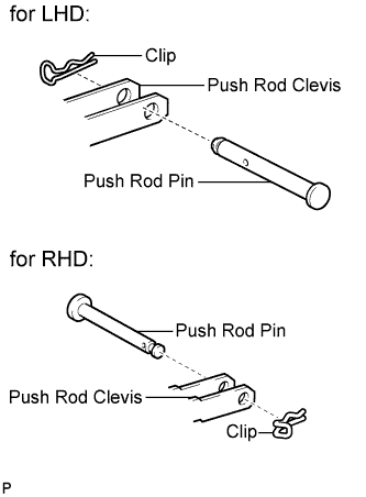
Remove the clip and push rod pin, then separate the push rod clevis.
-
-
REMOVE BRAKE BOOSTER ASSEMBLY
-
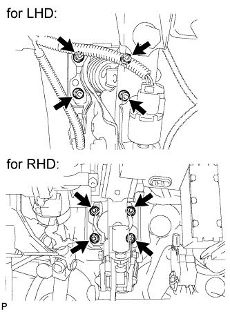
Remove the 4 nuts and brake booster assembly.
Note
Do not damage the brake lines.
-
-
REMOVE BRAKE BOOSTER GASKET
-
Remove the brake booster gasket from the brake booster assembly.
-
-
REMOVE BRAKE VACUUM CHECK VALVE ASSEMBLY
-
Remove the brake vacuum check valve assembly from the brake booster assembly.
-
-
REMOVE CHECK VALVE GROMMET
-
Remove the check valve grommet from the brake booster assembly.
-
-
REMOVE BRAKE MASTER CYLINDER PUSH ROD CLEVIS
-
Remove the lock nut and brake master cylinder push rod clevis.
-