BRAKE MASTER CYLINDER INSTALLATION

-
INSPECT AND ADJUST BRAKE BOOSTER PUSH ROD
Note
Make an adjustment with no vacuum in the brake booster assembly. (Depress the brake pedal several times with the engine stopped.)
Tech Tips
-
Adjustment of the brake booster push rod is required when the brake master cylinder sub-assembly is replaced with a new one.
-
Adjustment is not necessary when the removed brake master cylinder sub-assembly is reused and the brake booster assembly is replaced with a new one.
-
Apply chalk to the tip of the accessory tool.
Tech Tips
An accessory tool is enclosed with a new brake master cylinder sub-assembly.
-
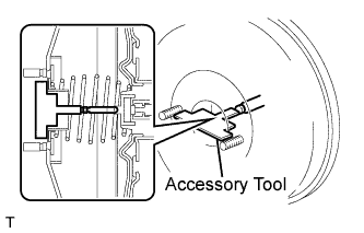
Place the accessory tool on the brake booster assembly.
-
Measure the clearance between the brake booster push rod and accessory tool.
Standard clearance 0 mm (0 in.) Tech Tips
Adjust the clearance in the following cases:
-
If there is a clearance between the accessory tool and the shell of the brake booster (floating accessory tool), the push rod is protruding too far.
-
If the chalk does not stick on the tip of the brake booster push rod, the push rod protrusion is insufficient.
-
-
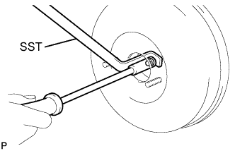
If the clearance is not as specified, adjust the push rod length by holding the rod using SST and turning the tip of the rod using a socket driver (7 mm, 0.28 in.).
- SST
- 09737-00020
Tech Tips
Check the push rod clearance again after adjustment.
-
-
INSTALL BRAKE MASTER CYLINDER SUB-ASSEMBLY (for LHD)
-
Install a new O-ring to the brake master cylinder sub-assembly.
-
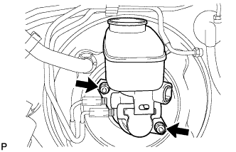
Install the brake master cylinder sub-assembly to the brake booster assembly with the 2 nuts.
- Torque:
- 13 N*m { 133 kgf*cm, 10 ft.*lbf }
-
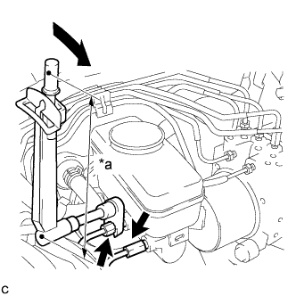
Text in Illustration *a Fulcrum Length Using a union nut wrench (10 mm), connect the 2 brake lines to the brake master cylinder sub-assembly.
- Torque:
- without a union nut wrench
- 15 N*m { 153 kgf*cm, 11 ft.*lbf }
- with a union nut wrench
- 14 N*m { 143 kgf*cm, 10 ft.*lbf }
Note
-
Use a torque wrench with a fulcrum length of 250 mm (9.84 in.).
-
This torque value is effective when the union nut wrench is parallel to the torque wrench.
-
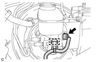
Engage the clamp and connect the connector.
-
-
INSTALL BRAKE MASTER CYLINDER SUB-ASSEMBLY (for RHD)
-
Install a new O-ring to the brake master cylinder sub-assembly.
-
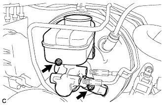
Install the brake master cylinder sub-assembly and wire harness clamp bracket to the booster assembly with the 2 nuts.
- Torque:
- 13 N*m { 133 kgf*cm, 10 ft.*lbf }
-
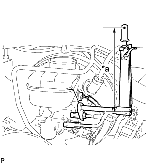
Text in Illustration *a Fulcrum Length Using a union nut wrench (10 mm), connect the 2 brake lines to the brake master cylinder sub-assembly.
- Torque:
- without a union nut wrench
- 15 N*m { 153 kgf*cm, 11 ft.*lbf }
- with a union nut wrench
- 14 N*m { 143 kgf*cm, 10 ft.*lbf }
Note
-
Use a torque wrench with a fulcrum length of 250 mm (9.84 in.)
-
This torque value is effective when the union nut wrench is parallel to the torque wrench.
-
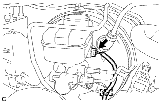
Engage the clamp and connect the connector.
-
-
INSTALL NO. 3 ENGINE ROOM RELAY BLOCK (for LHD)
-
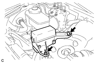
Install the No. 3 engine room relay block with the bolt and nut.
- Torque:
- 8.0 N*m { 82 kgf*cm, 71 in.*lbf }
-
-
INSTALL NO. 3 ENGINE ROOM RELAY BLOCK (for RHD)
-
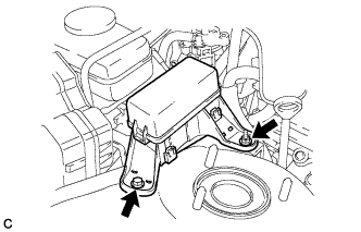
Install the No. 3 engine room relay block with the bolt and nut.
- Torque:
- 8.0 N*m { 82 kgf*cm, 71 in.*lbf }
-
-
CONNECT CABLE TO NEGATIVE BATTERY TERMINAL
Note
When disconnecting the cable, some systems need to be initialized after the cable is reconnected Click here.
-
BLEED BRAKE SYSTEM
Tech Tips
-
INSTALL ENGINE ROOM SIDE COVER LH (for LHD)
-

Install the engine room side cover LH with the 5 clips.
-
-
INSTALL ENGINE ROOM SIDE COVER RH (for RHD)
-
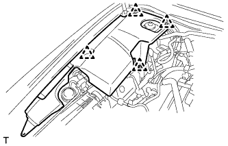
Install the engine room side cover RH with the 4 clips.
-
-
INSTALL COOL AIR INTAKE DUCT SEAL
-
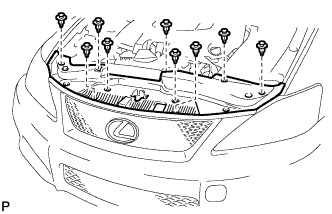
Install the cool air intake duct seal with the 9 clips.
-