YAW RATE AND ACCELERATION SENSOR REMOVAL

-
DISCONNECT CABLE FROM NEGATIVE BATTERY TERMINAL
Note
When disconnecting the cable, some systems need to be initialized after the cable is reconnected Click here.
-
REMOVE SHIFT LEVER KNOB SUB-ASSEMBLY
-
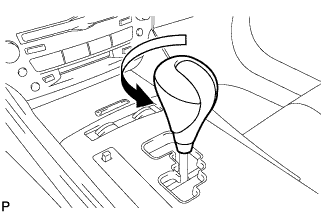
Turn the shift lever knob counterclockwise and remove the shift lever knob sub-assembly.
-
-
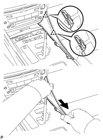
REMOVE UPPER NO. 1 CONSOLE PANEL GARNISH
-
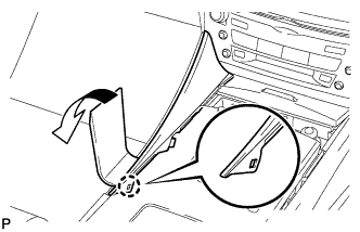
Using a moulding remover, disengage the claw.
-
Pull the upper No. 1 console panel garnish in the direction indicated by the arrow to disengage the 2 clips and remove it.
-
-
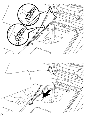
REMOVE UPPER NO. 2 CONSOLE PANEL GARNISH
-
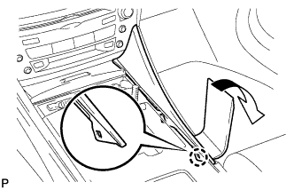
Using a moulding remover, disengage the claw.
-
Pull the upper No. 2 console panel garnish in the direction indicated by the arrow to disengage the 2 clips and remove it.
-
-
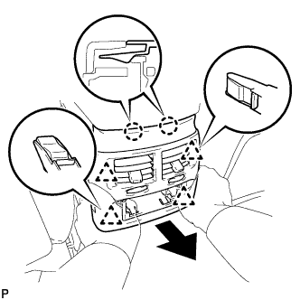
REMOVE CONSOLE PANEL SUB-ASSEMBLY
-
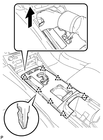
Hold the front of the console panel sub-assembly as shown in the illustration and disengage the 8 clips by pulling the console panel sub-assembly in the direction shown by the arrow.
Note
Do not use any tools to disengage the clips. The use of tools may result in damage to the console panel sub-assembly.
-
Disconnect the connectors and remove the console panel sub-assembly.
-
-
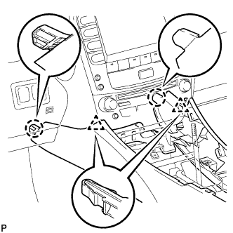
REMOVE FRONT ASH RECEPTACLE ASSEMBLY
-
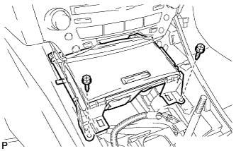
Remove the 2 screws <E>.
-
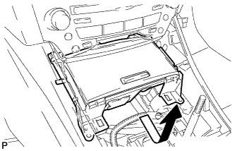
Pull the front ash receptacle assembly in the direction indicated by the arrow to disconnect the connectors and remove it.
-
-
REMOVE REAR ASH RECEPTACLE ASSEMBLY
-
Remove the rear ash receptacle assembly.
-
-
REMOVE CONSOLE BOX REGISTER ASSEMBLY
-
Disengage the 2 claws and 4 clips, and then remove the console box register assembly.
-
-
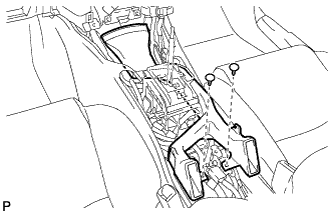
REMOVE CONSOLE BOX
-
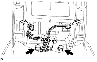
Remove the 2 bolts.
-
Disconnect the 2 connectors.
-
Disengage the 2 clamps.
-
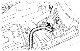
Remove the 2 bolts.
-
Disconnect the connector.
-
Remove the 2 bolts.
-
Disengage the 2 claws and 2 clips, and then remove the console box.
-
-
REMOVE NO. 2 CONSOLE BOX DUCT
-
Remove the 2 clips and No. 2 console box duct.
-
-
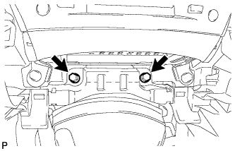
REMOVE YAW RATE AND ACCELERATION SENSOR
-
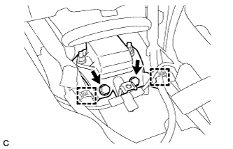
Separate the 2 wire harness clamps.
-
Remove the 2 bolts and yaw rate and acceleration sensor.
-
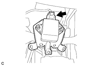
Disconnect the yaw rate and acceleration sensor connector.
Note
Do not remove the sensor from the bracket.
-