FRONT SPEED SENSOR INSTALLATION

-
INSTALL FRONT SPEED SENSOR
-
Wipe off sealant attached to the front speed sensor's fitting surface with a non-residue solvent.
Note
Prevent foreign matter from attaching to the sensor rotor.
-
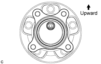
Install a new front speed sensor to the front axle hub and bearing assembly. The front speed sensor connector should be positioned upward.
-
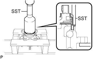
Using SST and a press, install the front speed sensor onto the front axle hub and bearing assembly.
- SST
- 09214-76011
Note
-
Keep the front speed sensor away from magnets.
-
Do not use a hammer on the front speed sensor.
-
Check that there is no foreign matter such as iron chips on the front speed sensor's detecting portion.
-
Slowly press the front speed sensor straight.
-
-
INSTALL FRONT AXLE HUB SUB-ASSEMBLY WITH FRONT SPEED SENSOR
-
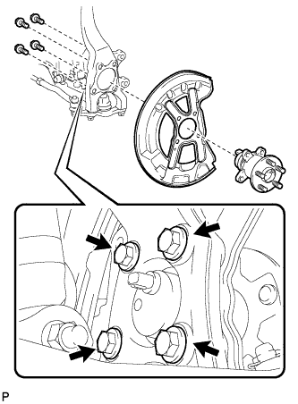
Temporarily install the front axle hub sub-assembly and front disc brake dust cover with the 4 bolts.
-
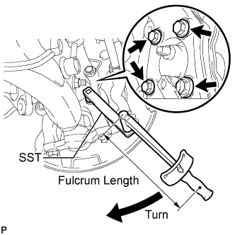
Using SST and a socket wrench (17 mm), fully tighten the 4 bolts.
- SST
- 09961-00950
- Torque:
- without SST
- 69 N*m { 700 kgf*cm, 51 ft.*lbf }
- with SST
- 51 N*m { 517 kgf*cm, 37 ft.*lbf }
Note
-
Use a torque wrench with a fulcrum length of 425 mm (16.73 in.).
-
This torque value is effective when SST is parallel to the torque wrench.
-
-
INSPECT FRONT AXLE HUB BEARING FOR LOOSENESS
-
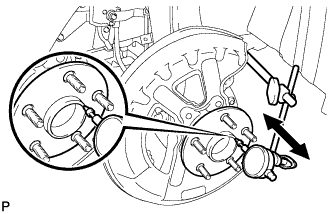
Using a dial indicator, check for looseness near the center of the front axle hub.
Maximum looseness 0.05 mm (0.00196 in.) Note
Ensure that the dial indicator is perpendicular to the measurement surface.
If the looseness exceeds the maximum, replace the front axle hub and bearing assembly.
-
-
INSPECT FRONT AXLE HUB FOR RUNOUT
-
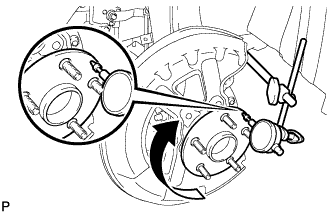
Using a dial indicator, check for runout on the surface of the axle hub outside the hub bolt.
Maximum runout 0.05 mm (0.00196 in.) Note
Ensure that the dial indicator is set perpendicular to the measurement surface.
If the runout exceeds the maximum, replace the front axle hub and bearing assembly.
-
-
INSTALL FRONT DISC
-
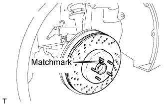
Align the matchmarks of the disc and axle hub, and install the front disc.
Note
When replacing the disc with a new one, select the installation position where the front disc has minimal runout.
-
-
INSTALL FRONT DISC BRAKE CYLINDER ASSEMBLY
-
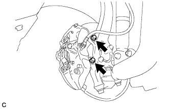
Install the front disc brake cylinder assembly with the 2 bolts.
- Torque:
- 78 N*m { 795 kgf*cm, 58 ft.*lbf }
Note
Do not twist the brake hose when installing the front disc brake cylinder assembly.
-
-
CONNECT FRONT SPEED SENSOR WIRE
-
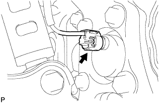
Connect the front speed sensor wire to the front speed sensor.
Note
Do not twist the sensor wire.
-
-
INSTALL FRONT WHEEL
- Torque:
- 103 N*m { 1050 kgf*cm, 76 ft.*lbf }
-
CHECK FOR SPEED SENSOR SIGNAL
Tech Tips