BRAKE ACTUATOR INSTALLATION

-
INSTALL BRAKE ACTUATOR BRACKET (for LHD)
-
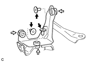
Install the 3 brake actuator bolt case cushions and 3 brake actuator bolt collars to the brake actuator bracket.
-
-
INSTALL BRAKE ACTUATOR BRACKET (for RHD)
-
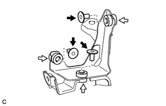
Install the 3 brake actuator bolt case cushions and 3 brake actuator collars to the brake actuator bracket assembly.
-
-
INSTALL BRAKE ACTUATOR ASSEMBLY (for LHD)
-
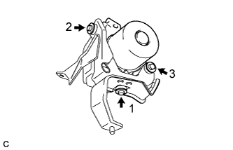
Install the brake actuator assembly to the brake actuator bracket with the 3 bolts.
- Torque:
- 5.4 N*m { 55 kgf*cm, 48 in.*lbf }
Note
-
If installing a new brake actuator, do not remove the hole plugs before connecting the 6 brake lines because the brake actuator is filled with brake fluid.
-
Do not carry the brake actuator assembly by the connector.
-
Tighten the 3 bolts in the order shown in the illustration.
-
-
INSTALL BRAKE ACTUATOR ASSEMBLY (for RHD)
-
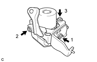
Install the brake actuator assembly to the brake actuator bracket assembly with the 3 bolts.
- Torque:
- 5.4 N*m { 55 kgf*cm, 48 in.*lbf }
Note
-
If installing a new brake actuator, do not remove the hole plugs before connecting the 6 brake lines because the brake actuator is filled with brake fluid.
-
Do not carry the brake actuator assembly by the connector.
-
Tighten the 3 bolts in the order shown in the illustration.
-
-
TEMPORARILY INSTALL BRAKE ACTUATOR WITH BRACKET (for LHD)
-
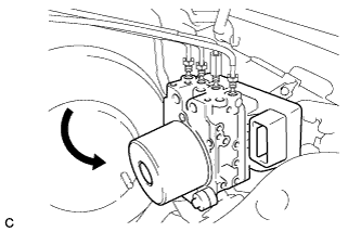
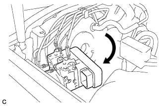
Temporarily install the brake actuator with bracket.
-
-
TEMPORARILY INSTALL BRAKE ACTUATOR WITH BRACKET (for RHD)
-

Temporarily install the brake actuator with bracket.
-
-
INSTALL BRAKE ACTUATOR WITH BRACKET (for LHD)
-
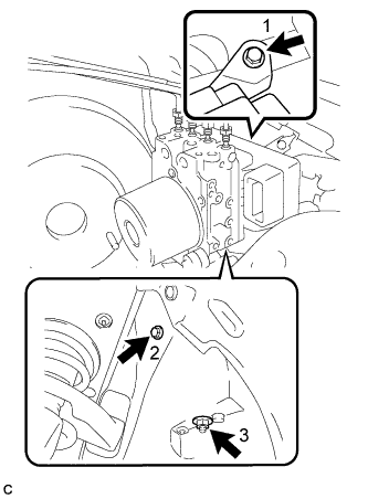
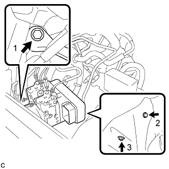
Install the brake actuator with bracket to the body with the 2 bolts and nut.
- Torque:
- 19 N*m { 194 kgf*cm, 14 ft.*lbf }
Note
-
Do not damage the brake lines or wire harness.
-
Tighten the 2 bolts and nut in the order shown in the illustration.
-
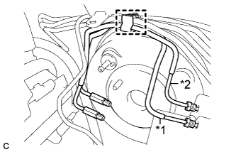
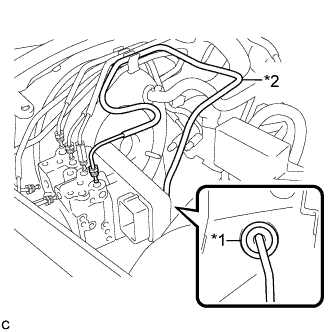
Text in Illustration *1 Front No. 1 Brake Line *2 Rear No. 1 Brake Line Install the front No. 1 brake line and rear No. 1 brake line to the clamp.
-
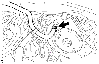
Connect the vacuum hose to the check valve with the clip.
-
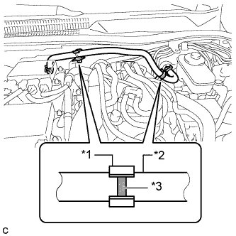
Text in Illustration *1 Clamp *2 Vacuum Hose *3 Mark Engage the clamps and inspect the condition of the vacuum hose.
Note
Align the vacuum hose matchmarks and the clamp as shown in the illustration.
-
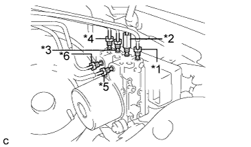
Text in Illustration *1 to Front Wheel Cylinder RH *2 to Front Wheel Cylinder LH *3 to Rear Wheel Cylinder RH *4 to Rear Wheel Cylinder LH *5 from 1st Master Cylinder Chamber *6 from 2nd Master Cylinder Chamber Temporarily tighten each brake line to the correct positions of the brake actuator assembly with bracket as shown in the illustration.
-
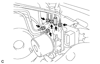
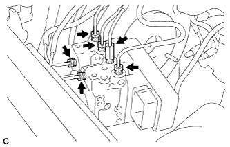
Using a union nut wrench, fully tighten each brake line.
- Torque:
- 15 N*m { 153 kgf*cm, 11 ft.*lbf }
Note
-
This torque value is effective when the union nut wrench is parallel to the torque wrench.
-
Use the formula to calculate special torque values for situations where the union nut wrench is combined with a torque wrench Click here.
-
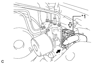
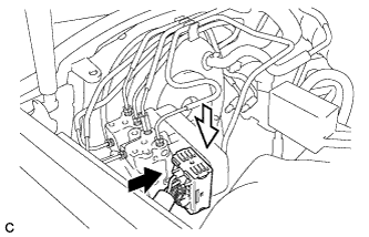
Text in Illustration *1 Lock Lever Connect the brake actuator connector.
Note
-
Make sure that the actuator connector can be connected smoothly. Do not allow water, oil or dirt to enter.
-
Make sure that the connector is locked securely.
-
-
-
INSTALL BRAKE ACTUATOR WITH BRACKET (for RHD)
-
Temporarily install the brake actuator assembly with bracket.
-
Install the brake actuator with bracket to the body with the 2 bolts and nut.
- Torque:
- 19 N*m { 194 kgf*cm, 14 ft.*lbf }
Note
-
Do not damage the brake lines or wire harness.
-
Tighten the 2 bolts and nut in the order shown in the illustration.
-
Text in Illustration *1 Grommet *2 Front No. 2 Brake Line Install the front No. 2 brake line and grommet.
Note
Make sure that the grommet is installed correctly.
-
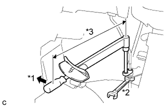
Text in Illustration *1 Turn *2 Hold *3 Fulcrum Length Using a union nut wrench (10 mm), connect the brake line to the front flexible hose while holding the flexible hose with a wrench.
- Torque:
- 15 N*m { 155 kgf*cm, 11 ft.*lbf }
Note
-
Do not kink or damage the brake lines.
-
Do not allow any foreign matter such as dirt or dust to enter the brake line from the clip or bracket.
-
This torque value is effective when the union nut wrench is parallel to the torque wrench.
-
Use the formula to calculate special torque values for situations where the union nut wrench is combined with a torque wrench Click here.
-
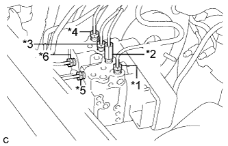
Text in Illustration *1 to Front Wheel Cylinder RH *2 to Front Wheel Cylinder LH *3 to Rear Wheel Cylinder RH *4 to Rear Wheel Cylinder LH *5 from 1st Master Cylinder Chamber *6 from 2nd Master Cylinder Chamber Temporarily tighten each brake tube to the correct position of the brake actuator assembly with bracket as shown in the illustration.
-
Using a union nut wrench, fully tighten each brake line.
- Torque:
- 15 N*m { 155 kgf*cm, 11 ft.*lbf }
Note
-
This torque value is effective when the union nut wrench is parallel to the torque wrench.
-
Use the formula to calculate special torque values for situations where the union nut wrench is combined with a torque wrench Click here.
-
Connect the brake actuator connector.
Note
-
Make sure that the actuator connector can be connected smoothly. Do not allow water, oil or dirt to enter.
-
Make sure that the connector is locked securely.
-
-
-
INSTALL BRAKE MASTER CYLINDER SUB-ASSEMBLY (for LHD)
Tech Tips
Refer to the procedure from Install Brake Master Cylinder Sub-assembly Click here.
-
INSTALL BRAKE MASTER CYLINDER SUB-ASSEMBLY (for RHD)
Tech Tips
Refer to the procedure from Install Brake Master Cylinder Sub-assembly Click here.
-
OBTAIN ZERO POINT OF YAW RATE AND ACCELERATION SENSOR
Tech Tips
Obtain zero point of the yaw rate and acceleration sensor Click here.
-
CHECK FOR SENSOR SIGNAL
Tech Tips
Check for sensor signal Click here.
-
INSPECT ACTUATOR USING INTELLIGENT TESTER
Tech Tips