VEHICLE STABILITY CONTROL SYSTEM, Diagnostic DTC:C1409, C1410

| DTC Code | DTC Name |
|---|---|
| C1409 | Front Speed Sensor RH Performance |
| C1410 | Front Speed Sensor LH Performance |
DESCRIPTION
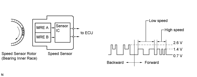
The speed sensor detects the wheel speed and sends the appropriate signals to the skid control ECU. These signals are used for the ABS control system. This speed sensor contains a sensor IC, which consists of 2 MREs (Magnetic Resistance Elements). The speed sensor rotor, which consists of 48 sets of N and S poles arranged in a circle, is integrated with the inner race of the hub bearing.
To detect the rotation direction, the output waves are used to determine the relationship of the pulses that are generated by the 2 MREs. Upon receiving this signal, the sensor IC outputs a forward or backward waveform to the ECU.
| DTC Code | DTC Detection Condition | Trouble Area |
|---|---|---|
| C1409 C1410 |
Any of the following is detected:
|
Front speed sensor RH/LH |
Tech Tips
-
DTC C1409 is for the front speed sensor RH.
-
DTC C1410 is for the front speed sensor LH.
WIRING DIAGRAM
Refer to DTCs C1401 and C1402 Click here.
INSPECTION PROCEDURE
PROCEDURE
-
REPLACE FRONT SPEED SENSOR
-
Replace the front speed sensor and the front axle hub sub-assembly (front speed sensor rotor) Click here.
Tech Tips
The front speed sensor rotor is incorporated into the front axle hub sub-assembly.
If the front speed sensor rotor needs to be replaced, replace it together with the front axle hub sub-assembly with front speed sensor.
Note
Check the speed sensor signal after replacement Click here.
Tech Tips
If troubleshooting has been carried out according to Problem Symptoms Table, refer back to the table and proceed to the next step Click here.
NEXT 
END
-