VEHICLE STABILITY CONTROL SYSTEM, Diagnostic DTC:C1249/49

| DTC Code | DTC Name |
|---|---|
| C1249/49 | Open in Stop Light Switch Circuit |
DESCRIPTION
The skid control ECU inputs the stop light switch signal and the condition of brake operation.
The skid control ECU has an open detection circuit, which outputs this DTC when an open circuit is detected in the stop light switch input circuit while the stop light switch is OFF.
| DTC Code | DTC Detection Condition | Trouble Area |
|---|---|---|
| C1249/49 | Either of the following is detected:
|
|
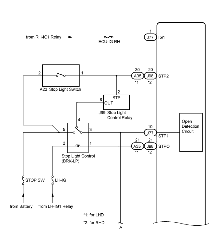
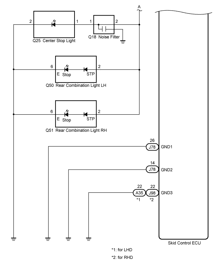
WIRING DIAGRAM
INSPECTION PROCEDURE
Note
When replacing the skid control ECU, perform zero point calibration and store system information Click here.
PROCEDURE
-
CHECK STOP LIGHT OPERATION
-
Check that the stop lights come on when the brake pedal is depressed, and go off when the brake pedal is released.
OK Condition Illumination Condition Brake pedal depressed ON Brake pedal released OFF
NG 
INSPECT STOP SW FUSE Click here
OK 
-
-
READ VALUE USING INTELLIGENT TESTER (STOP LIGHT SWITCH AND BRAKE PEDAL LOAD SENSING SWITCH)
-
Connect the intelligent tester to the DLC3.
-
Turn the engine switch on (IG).
-
Select the Data List mode on the intelligent tester Click here.
ABS/VSC/TRC Tester Display Measurement Item / Range Normal Condition Diagnostic Note Stop Light SW Stop light switch / ON or OFF ON: Brake pedal depressed
OFF: Brake pedal released
- Brake Pedal Load Sensing SW Brake pedal load sensing switch / ON or OFF ON: Brake pedal depressed beyond the specified point
OFF: Brake pedal not depressed beyond the specified point
- -
Check that the stop light display observed on the intelligent tester changes when the brake pedal is depressed.
OK When the brake pedal is depressed, the intelligent tester displays "ON". -
Depress the brake pedal slowly, and check when the stop light switch and brake pedal load sensing switch turn ON.
OK First the stop light switch should turn ON, and then the brake pedal load sensing switch should turn ON. Result Result Proceed to OK A NG (The stop light switch does not turn on) B NG (The brake pedal load sensing switch turns on first) C
B
CHECK HARNESS AND CONNECTOR (SKID CONTROL ECU - ENGINE ROOM NO. 3 RELAY BLOCK) Click here
C
CHECK BRAKE PEDAL AND STOP LIGHT SWITCH INSTALLATION Click here
A
-
-
INSPECT SKID CONTROL ECU (IG1 TERMINAL)
-
Turn the engine switch off.
-
Make sure that there is no looseness at the locking part and the connecting part of the connector.
-
Disconnect the skid control ECU connector.
-
Turn the engine switch on (IG).
-
Measure the voltage according to the value(s) in the table below.
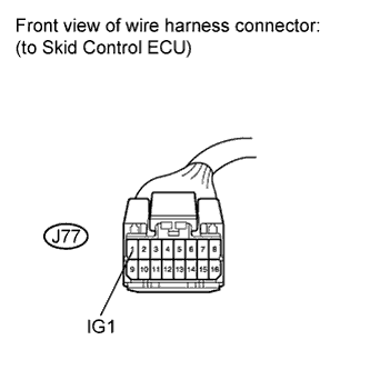
Standard Voltage Tester Connection Switch Condition Specified Condition J77-1 (IG1) - Body ground Engine switch on (IG) 11 to 14 V
NG 
REPAIR OR REPLACE HARNESS OR CONNECTOR (IG1 CIRCUIT)
OK
-
-
INSPECT SKID CONTROL ECU (GND TERMINAL)
-
Turn the engine switch off.
-
Make sure that there is no looseness at the locking part and the connecting part of the connectors.
-
Disconnect the skid control ECU connectors.
-
Measure the resistance according to the value(s) in the table below.
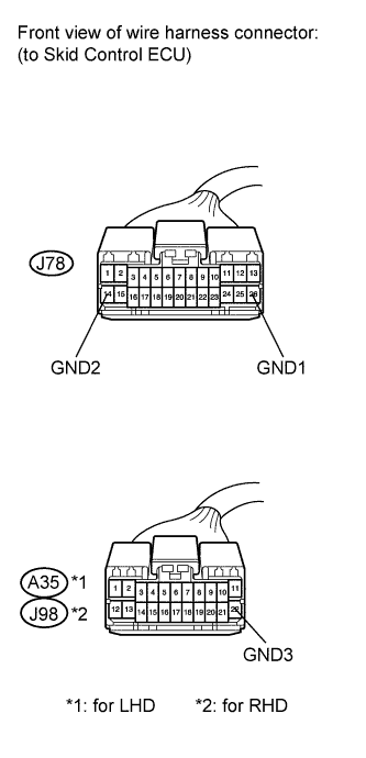
Standard Resistance Tester Connection Condition Specified Condition J78-26 (GND1) - Body ground Always Below 1 Ω J78-14 (GND2) - Body ground Always Below 1 Ω A35*1, J98*2-22 (GND3) - Body ground Always Below 1 Ω *1: for LHD
*2: for RHD
NG
REPAIR OR REPLACE HARNESS OR CONNECTOR (GND CIRCUIT)
OK
-
-
RECONFIRM DTC
-
Reconnect the skid control ECU connectors.
-
Clear the DTCs Click here.
-
Start the engine.
-
Depress the brake pedal several times to test the stop light circuit.
-
Check if the same DTC is recorded Click here.
Result Result Proceed to DTC (C1249/49) is not output A DTC (C1249/49) is output B Tech Tips
If troubleshooting has been carried out according to Problem Symptoms Table, refer back to the table and proceed to the next step Click here.
B
REPLACE SKID CONTROL ECU Click here
A 
CHECK FOR INTERMITTENT PROBLEMS (SYMPTOM SIMULATION) Click here
-
-
INSPECT STOP SW FUSE
-
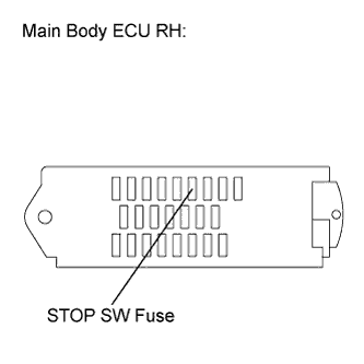
Remove the STOP SW fuse from the main body ECU RH (cowl side junction block RH).
-
Measure the resistance according to the value(s) in the table below.
Standard Resistance Tester Connection Condition Specified Condition STOP SW (7.5 A) fuse Always Below 1 Ω
NG
REPLACE STOP SW FUSE
OK
-
-
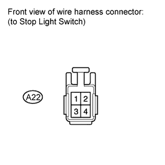
INSPECT STOP LIGHT SWITCH (POWER SOURCE TERMINAL)
-
Install the STOP SW fuse.
-
Make sure that there is no looseness at the locking part and the connecting part of the connector.
-
Disconnect the stop light switch connector.
-
Measure the voltage according to the value(s) in the table below.
Standard Voltage Tester Connection Condition Specified Condition A22-2 - Body ground Always 11 to 14 V
NG
REPAIR OR REPLACE HARNESS OR CONNECTOR (POWER SOURCE CIRCUIT)
OK
-
-
INSPECT STOP LIGHT SWITCH
-
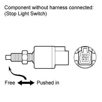
Measure the resistance according to the value(s) in the table below.
Standard Resistance Tester Connection Switch Condition Specified Condition 1 - 2 Switch pin free Below 1 Ω 1 - 2 Switch pin pushed in 10 kΩ or higher
NG
REPLACE STOP LIGHT SWITCH Click here
OK
-
-
INSPECT STOP LIGHT CONTROL RELAY (BRK-LP)
-
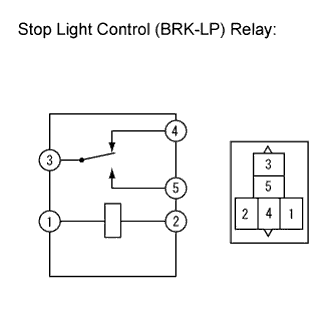
Remove the stop light control (BRK-LP) relay.
-
Measure the resistance according to the value(s) in the table below.
Standard Resistance Tester Connection Condition Specified Condition 3 - 4 Voltage is not applied between terminals 1 and 2 Below 1 Ω
NG
REPLACE STOP LIGHT CONTROL RELAY (BRK-LP)
OK
-
-
INSPECT STOP LIGHT CONTROL RELAY
-
Check the stop light control relay Click here.
OK The stop light control relay is normal.
NG
REPLACE STOP LIGHT CONTROL RELAY Click here
OK
-
-
CHECK HARNESS AND CONNECTOR (STOP LIGHT SWITCH - STOP LIGHT CONTROL RELAY)
-
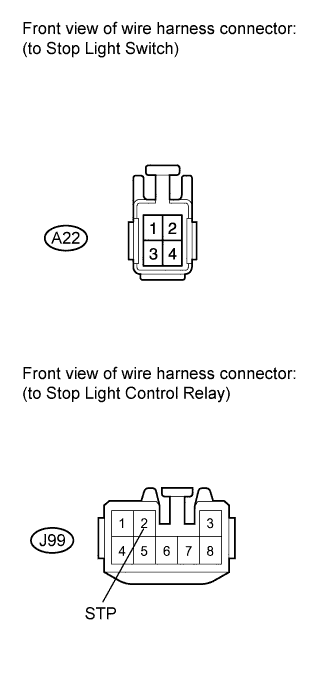
Make sure that there is no looseness at the locking part and the connecting part of the connector.
-
Disconnect the stop light control relay connector.
-
Measure the resistance according to the value(s) in the table below.
Standard Resistance Tester Connection Condition Specified Condition A22-1 - J99-2 (STP) Always Below 1 Ω A22-1 - Body ground Always 10 kΩ or higher
NG
REPAIR OR REPLACE HARNESS OR CONNECTOR
OK
-
-
CHECK HARNESS AND CONNECTOR (STOP LIGHT CONTROL RELAY - ENGINE ROOM NO. 3 RELAY BLOCK)
-
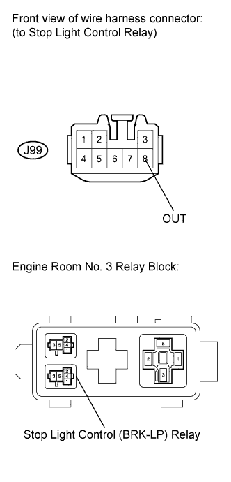
Measure the resistance according to the value(s) in the table below.
Standard Resistance Tester Connection Condition Specified Condition J99-8 (OUT) - Stop light control (BRK-LP) relay terminal 4 Always Below 1 Ω J99-8 (OUT) - Body ground Always 10 kΩ or higher
NG
REPAIR OR REPLACE HARNESS OR CONNECTOR
OK
-
-
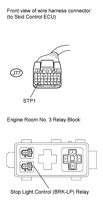
CHECK HARNESS AND CONNECTOR (SKID CONTROL ECU - ENGINE ROOM NO. 3 RELAY BLOCK)
-
Make sure that there is no looseness at the locking part and the connecting part of the connector.
-
Disconnect the skid control ECU connector.
-
Measure the resistance according to the value(s) in the table below.
Standard Resistance Tester Connection Condition Specified Condition J77-10 (STP1) - Stop light control (BRK-LP) relay terminal 3 Always Below 1 Ω
NG
REPAIR OR REPLACE HARNESS OR CONNECTOR
OK
-
-
RECONFIRM DTC
-
Clear the DTCs Click here.
-
Start the engine.
-
Depress the brake pedal several times to test the stop light circuit.
-
Check if the same DTC is recorded Click here.
Tech Tips
Reinstall the relay, connectors, etc. and restore the vehicle to its prior condition before rechecking for DTCs.
Result Result Proceed to DTC (C1249/49) is not output A DTC (C1249/49) is output B Tech Tips
If troubleshooting has been carried out according to Problem Symptoms Table, refer back to the table and proceed to the next step Click here.
B
REPLACE SKID CONTROL ECU Click here
A
INSPECT LIGHTING SYSTEM (STOP LIGHT CIRCUIT) Click here
-
-
CHECK HARNESS AND CONNECTOR (SKID CONTROL ECU - ENGINE ROOM NO. 3 RELAY BLOCK)
-
Turn the engine switch off.
-
Remove the stop light control (BRK-LP) relay.
-
Make sure that there is no looseness at the locking part and the connecting part of the connector.
-
Disconnect the skid control ECU connector.
-
Measure the resistance according to the value(s) in the table below.
Standard Resistance Tester Connection Condition Specified Condition J77-10 (STP1) - Stop light control (BRK-LP) relay terminal 3 Always Below 1 Ω Tech Tips
If troubleshooting has been carried out according to Problem Symptoms Table, refer back to the table and proceed to the next step Click here.
NG
REPAIR OR REPLACE HARNESS OR CONNECTOR
OK
REPLACE SKID CONTROL ECU Click here
-
-
CHECK BRAKE PEDAL AND STOP LIGHT SWITCH INSTALLATION
-
Turn the engine switch off.
-
Check the brake pedal height and stop light switch installation Click here.
OK The brake pedal height and stop light switch installation are normal. Tech Tips
If troubleshooting has been carried out according to Problem Symptoms Table, refer back to the table and proceed to the next step Click here.
NG
ADJUST BRAKE PEDAL OR STOP LIGHT SWITCH Click here
OK
REPLACE BRAKE PEDAL SUPPORT ASSEMBLY (BRAKE PEDAL LOAD SENSING SWITCH) Click here
-