VEHICLE STABILITY CONTROL SYSTEM, Diagnostic DTC:C1246/46, C1281/81

| DTC Code | DTC Name |
|---|---|
| C1246/46 | Master Cylinder Pressure Sensor Malfunction |
| C1281/81 | Master Cylinder Pressure Sensor Output Malfunction (Test Mode DTC) |
DESCRIPTION
The master cylinder pressure sensor is built into the brake actuator assembly.
DTC C1281/81 will be deleted when the master cylinder pressure sensor sends a master cylinder pressure signal or when Test Mode ends. DTC C1281/81 is output only in Test Mode.
| DTC Code | DTC Detection Condition | Trouble Area |
|---|---|---|
| C1246/46 | Any of the following is detected:
|
|
| C1281/81 | Detected only during Test Mode. |
|
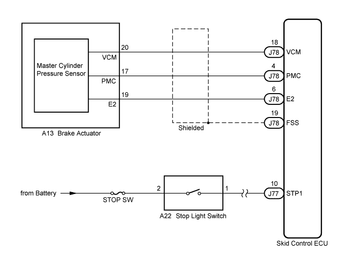
WIRING DIAGRAM
INSPECTION PROCEDURE
Note
When replacing the skid control ECU, perform zero point calibration and store system information Click here.
PROCEDURE
-
CHECK STOP LIGHT OPERATION
-
Check that the stop light comes on when the brake pedal is depressed, and goes off when the brake pedal is released.
OK Condition Illumination Condition Brake pedal depressed ON Brake pedal released OFF
NG 
INSPECT STOP LIGHT CIRCUIT Click here
OK 
-
-
READ VALUE USING INTELLIGENT TESTER (STOP LIGHT SWITCH AND BRAKE PEDAL LOAD SENSING SWITCH)
-
Connect the intelligent tester to the DLC3.
-
Turn the engine switch on (IG).
-
Select the Data List mode on the intelligent tester Click here.
ABS/VSC/TRC Tester Display Measurement Item / Range Normal Condition Diagnostic Note Stop Light SW Stop light switch / ON or OFF ON: Brake pedal depressed
OFF: Brake pedal released
- Brake Pedal Load Sensing SW Brake pedal load sensing switch / ON or OFF ON: Brake pedal depressed beyond the specified point
OFF: Brake pedal not depressed beyond the specified point
- -
Check that the stop light switch display and brake pedal load sensing switch display observed on the intelligent tester change according to brake pedal operation.
OK The intelligent tester displays ON or OFF according to brake pedal operation. -
Slowly depress the brake pedal, and check when the stop light switch and brake pedal load sensing switch turn ON.
OK The stop light switch should turn ON first, and then the brake pedal load sensing switch should turn ON. Result Result Proceed to OK A NG (The stop light switch does not turn on) B NG (The brake pedal load sensing switch turns on first) C
B 
INSPECT SKID CONTROL ECU (STP1 TERMINAL) Click here
C
CHECK BRAKE PEDAL AND STOP LIGHT SWITCH INSTALLATION Click here
A
-
-
READ VALUE USING INTELLIGENT TESTER (MASTER CYLINDER PRESSURE SENSOR)
-
Select the Data List mode on the intelligent tester Click here.
ABS/VSC/TRC Tester Display Measurement Item / Range Normal Condition Diagnostic Note Master Cylinder Sensor Master cylinder pressure sensor / min.: 0 V, max.: 5 V When brake pedal is released: 0.3 to 0.9 V Reading increases when brake pedal is depressed -
Check that the brake fluid pressure value of the master cylinder pressure sensor observed on the intelligent tester changes when the brake pedal is depressed.
OK When the pedal is depressed, voltage displayed on the intelligent tester increases.
NG
CHECK HARNESS AND CONNECTOR (SKID CONTROL ECU - BRAKE ACTUATOR) Click here
OK
-
-
RECONFIRM DTC
-
Turn the engine switch off.
-
Clear the DTCs Click here.
-
Start the engine.
-
Drive the vehicle at a speed of 30 km/h (18 mph) or more and perform braking test (decelerate the vehicle by depressing the brake pedal).
-
Check if the same DTC is recorded Click here.
Result Result Proceed to DTC (C1246/46) is not output A DTC (C1246/46) is output B
B
REPLACE SKID CONTROL ECU Click here
A 
CHECK FOR INTERMITTENT PROBLEMS (SYMPTOM SIMULATION) Click here
-
-
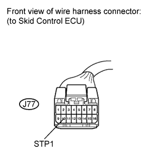
INSPECT SKID CONTROL ECU (STP1 TERMINAL)
-
Turn the engine switch off.
-
Make sure that there is no looseness at the locking part and the connecting part of the connector.
-
Disconnect the skid control ECU connector.
-
Measure the voltage according to the value(s) in the table below.
Standard Voltage Tester Connection Switch Condition Specified Condition J77-10 (STP1) - Body ground Stop light switch ON (Brake pedal depressed) 8 to 14 V J77-10 (STP1) - Body ground Stop light switch OFF (Brake pedal released) Below 1.5 V
NG
REPAIR OR REPLACE HARNESS OR CONNECTOR (STP1 CIRCUIT)
OK
REPLACE SKID CONTROL ECU Click here
-
-
CHECK BRAKE PEDAL AND STOP LIGHT SWITCH INSTALLATION
-
Turn the engine switch off.
-
Check the brake pedal height and stop light switch installation Click here.
OK The brake pedal height and stop light switch installation are normal.
NG
ADJUST BRAKE PEDAL OR STOP LIGHT SWITCH Click here
OK
REPLACE BRAKE PEDAL SUPPORT ASSEMBLY (BRAKE PEDAL LOAD SENSING SWITCH) Click here
-
-
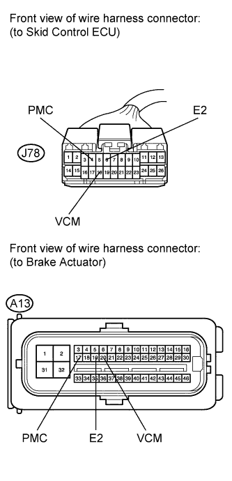
CHECK HARNESS AND CONNECTOR (SKID CONTROL ECU - BRAKE ACTUATOR)
-
Turn the engine switch off.
-
Make sure that there is no looseness at the locking part and the connecting part of the connectors.
-
Disconnect the skid control ECU connector and the brake actuator connector.
-
Measure the resistance according to the value(s) in the table below.
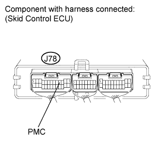
Standard Resistance Tester Connection Condition Specified Condition J78-18 (VCM) - A13-20 (VCM) Always Below 1 Ω J78-18 (VCM) - Body ground Always 10 kΩ or higher J78-4 (PMC) - A13-17 (PMC) Always Below 1 Ω J78-4 (PMC) - Body ground Always 10 kΩ or higher J78-6 (E2) - A13-19 (E2) Always Below 1 Ω J78-6 (E2) - Body ground Always 10 kΩ or higher
NG
REPAIR OR REPLACE HARNESS OR CONNECTOR
OK
-
-
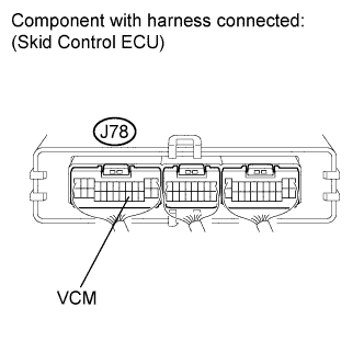
INSPECT SKID CONTROL ECU (SENSOR INPUT)
-
Reconnect the skid control ECU connector and the brake actuator connector.
-
Turn the engine switch on (IG).
-
Measure the voltage according to the value(s) in the table below.
Standard Voltage Tester Connection Switch Condition Specified Condition J78-18 (VCM) - Body ground Engine switch on (IG) 4.5 to 5.5 V
NG
REPLACE SKID CONTROL ECU Click here
OK
-
-
INSPECT SKID CONTROL ECU (SENSOR OUTPUT)
-
Remove either the right or left front brake cylinder bleeder plug.
-
Install the pressure gauge via the attachment, and bleed the gauge of air Click here.
-
Measure the voltage according to the value(s) in the table below.
Standard Voltage Tester Connection Fluid Pressure
MPa (kgf/cm2, psi)
Specified Condition J78-4 (PMC) - Body ground 0 (0, 0) 0.37 to 0.63 V J78-4 (PMC) - Body ground 5.88 (60, 853) 1.57 to 1.83 V J78-4 (PMC) - Body ground 11.8 (120, 1707) 2.77 to 3.03 V
NG
REPLACE BRAKE ACTUATOR ASSEMBLY Click here
OK
REPLACE SKID CONTROL ECU Click here
-