REAR UPPER ARM REMOVAL

Tech Tips
-
Use the same procedure for the RH side and LH side.
-
The procedure listed below is for the LH side.
-
REMOVE REAR WHEEL
-
REMOVE NO. 2 DIFFERENTIAL SUPPORT PROTECTOR
-
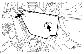
Remove the 2 nuts and No. 2 differential support protector.
-
-
SEPARATE REAR SHOCK ABSORBER WITH COIL SPRING
-
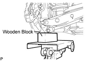
Support the rear axle assembly with a jack using a wooden block.
-
Remove the bolt and nut, and separate the rear shock absorber with coil spring from the rear No. 2 suspension arm assembly.
-
-
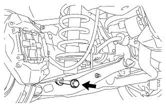
SEPARATE REAR STABILIZER LINK ASSEMBLY
-
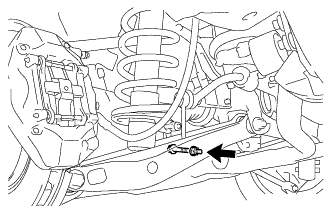
Remove the nut and bolt, and separate the rear stabilizer link assembly and the height control sensor link bracket from the rear No. 2 suspension arm.
-
-
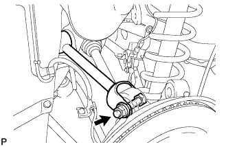
REMOVE REAR NO. 2 UPPER CONTROL ARM ASSEMBLY
-
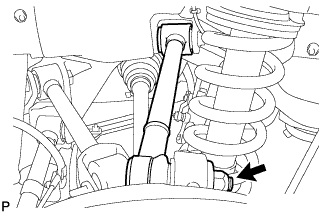
Remove the nut.
-
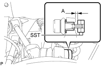
Install 2 spacers (SST spacer B) as shown in the illustration.
- SST
- 09960-20010 ( 09961-02060, 09961-02060 )
A 1 mm (0.0394 in.) or more Note
As SST may be damaged, make sure that the clearance between the arm and spacers is less than 1 mm (0.0394 in.).
-
Using SST, separate the rear No. 2 upper control arm assembly from the rear axle carrier sub-assembly as shown in the illustration.
- SST
- 09960-20010 ( 09961-02010, 09961-02060, 09961-02060 )
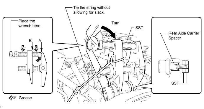
CAUTION:
Apply grease to the threads and end of the SST bolt.
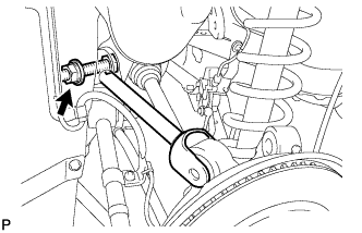
Note
-
Install SST so that A and B are parallel.
-
Be sure to place a wrench on the part indicated in the illustration.
-
Make sure that SST is securely positioned on the rear axle carrier.
-
Use caution not to damage the rear axle carrier sub-assembly because it is made of aluminum and may be damaged easily.
-
Do not damage the ball joint dust cover.
-
Make sure that the SST string is securely tied to the vehicle.
If the rear axle carrier spacer has come off, replace the rear axle carrier sub-assembly with a new one.
-
Remove the bolt, nut, washer, and rear No. 2 upper control arm assembly.
Tech Tips
Push the rear axle assembly downward.
-
-
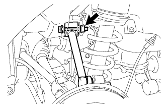
REMOVE REAR NO. 1 UPPER CONTROL ARM ASSEMBLY
-
Remove the bolt, nut, and washer, and separate the rear No. 1 upper control arm assembly from the rear axle carrier.
-
Remove the bolt, nut, washer, and rear No. 1 upper control arm assembly.
-