FRONT SUSPENSION MEMBER INSTALLATION

-
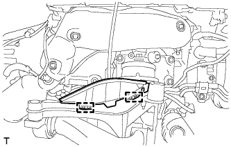
INSTALL POWER STEERING LINK ASSEMBLY
-
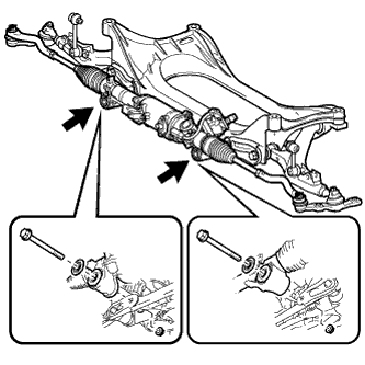
Install the power steering link assembly with the 2 bolts, 2 washers, and 2 nuts.
- Torque:
- 118 N*m { 1203 kgf*cm, 87 ft.*lbf }
Tech Tips
Install the power steering link assembly together with the front suspension lower arm assembly.
-
-
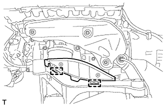
INSTALL FRONT LOWER SUSPENSION ARM ASSEMBLY LH
-
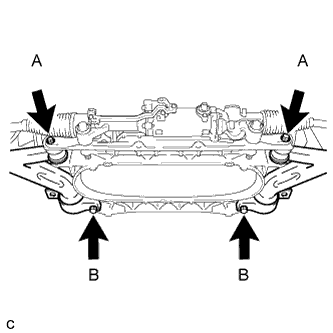
Install the front suspension lower arm assembly LH with the 2 bolts and washer.
- Torque:
- Bolt B
- 87 N*m { 887 kgf*cm, 64 ft.*lbf }
Tech Tips
Install the power steering link assembly together with the front lower suspension arm assembly.
-
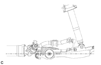
Set the front lower suspension arm in the horizontal position shown in the illustration.
-
Fully tighten the bolt A.
- Torque:
- Bolt A
- 135 N*m { 1377 kgf*cm, 100 ft.*lbf }
Note
The final torque must be applied under standard vehicle height conditions.
-
-
INSTALL FRONT LOWER SUSPENSION ARM ASSEMBLY RH
Tech Tips
Perform the same procedure as the LH side.
-
INSTALL FRONT STABILIZER BAR
-
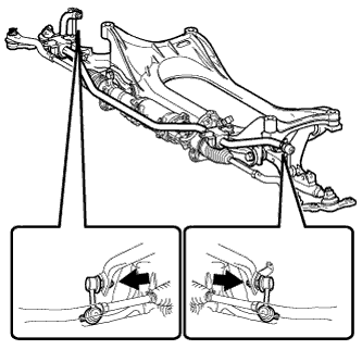
Install the front stabilizer bar with the 2 nuts.
- Torque:
- 84 N*m { 857 kgf*cm, 62 ft.*lbf }
Tech Tips
If the ball joint turns together with the nut, use a hexagon wrench (6 mm) to hold the stud bolt.
-
-
INSTALL FRONT ENGINE MOUNTING INSULATOR
-
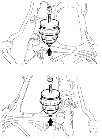
Install the 2 engine mounting insulators with the 2 nuts.
- Torque:
- 70 N*m { 714 kgf*cm, 52 ft.*lbf }
-
Install the 2 engine mounting spacers.
-
-
INSTALL FRONT SUSPENSION CROSSMEMBER SUB-ASSEMBLY
-
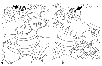
Install the front suspension crossmember sub-assembly with the 2 nuts.
- Torque:
- 35 N*m { 357 kgf*cm, 26 ft.*lbf }
-
-
INSTALL NO.2 EXHAUST MANIFOLD HEAT INSULATOR
-
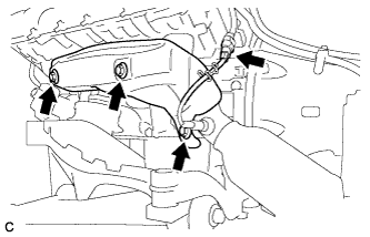
Install the No. 2 exhaust manifold heat insulator with the 3 bolts.
- Torque:
- 10 N*m { 102 kgf*cm, 7 ft.*lbf }
-
Connect the air fuel ratio sensor connector.
-
-
INSTALL NO.1 EXHAUST MANIFOLD HEAT INSULATOR
-
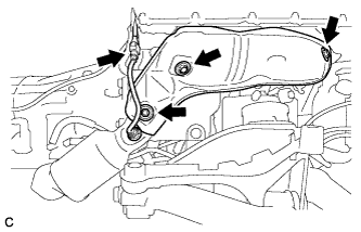
Install the No. 1 exhaust manifold heat insulator with the 3 bolts.
- Torque:
- 10 N*m { 102 kgf*cm, 7 ft.*lbf }
-
Connect the air fuel ratio sensor connector.
-
-
INSTALL ENGINE UNDER COVER SUB-ASSEMBLY LH
-
Install the engine under cover sub-assembly LH to the front suspension crossmember sub-assembly with the 2 clamps.
-
-
INSTALL ENGINE UNDER COVER SUB-ASSEMBLY RH
-
Install the engine under cover sub-assembly RH to the front suspension crossmember sub-assembly with the 2 clamps.
-
-
INSTALL OIL LEVEL DIPSTICK GUIDE
-
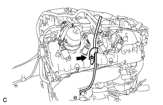
Apply engine oil to a new O-ring, and install it to the oil level dipstick guide sub-assembly.
-
Install the oil level dipstick guide sub-assembly with the bolt.
- Torque:
- 10 N*m { 102 kgf*cm, 7 ft.*lbf }
-
-
INSTALL OIL LEVEL DIPSTICK
-
INSTALL ENGINE WITH TRANSMISSION ASSEMBLY
Tech Tips
Install the engine with transmission assembly. Click here