FRONT SUSPENSION MEMBER REMOVAL

-
REMOVE ENGINE WITH TRANSMISSION ASSEMBLY
Tech Tips
Remove the engine with transmission assembly. Click here
-
INSTALL ENGINE HANGERS
-
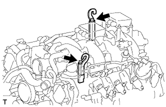
Install the 2 engine hangers with the 2 bolts as shown in the illustration.
Engine Hanger Part No. Item Part No. Engine hanger 12081-38020 Bolt 90119-14120 - Torque:
- 43 N*m { 438 kgf*cm, 32 ft.*lbf }
-
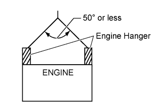
Attach an engine sling device and hang the engine with a chain block.
Note
When hanging the engine, make sure to hang the engine with the chains at an angle of 50° or less. Otherwise, the engine or engine hangers may be damaged.
-
-
REMOVE OIL LEVEL DIPSTICK
-
REMOVE OIL LEVEL DIPSTICK GUIDE
-
Remove the oil level dipstick sub-assembly.
-
-
REMOVE ENGINE UNDER COVER SUB-ASSEMBLY LH
-
Remove the 2 clamps and engine under cover sub-assembly LH from the front suspension crossmember sub-assembly.
-
-
REMOVE ENGINE UNDER COVER SUB-ASSEMBLY RH
-
Remove the 2 clamps and engine under cover sub-assembly RH from the front suspension crossmember sub-assembly.
-
-
REMOVE NO.1 EXHAUST MANIFOLD HEAT INSULATOR
-
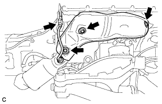
Disconnect the air fuel ratio sensor connector.
-
Remove the 3 bolts and No. 1 exhaust manifold heat insulator.
-
-
REMOVE NO.2 EXHAUST MANIFOLD HEAT INSULATOR
-
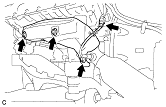
Disconnect the air fuel ratio sensor connector.
-
Remove the 3 bolts and No. 2 exhaust manifold heat insulator.
-
-
REMOVE FRONT SUSPENSION CROSSMEMBER SUB-ASSEMBLY
-
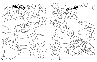
Remove the 2 nuts, then remove the front suspension crossmember sub-assembly from the engine.
-
-
REMOVE FRONT ENGINE MOUNTING INSULATOR
-
Remove the 2 engine mounting spacers.
-
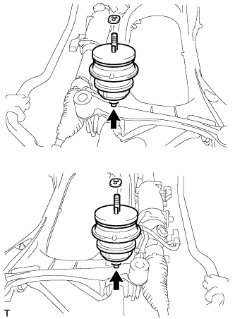
Remove the 2 nuts and 2 front engine mounting insulators from the front suspension crossmember sub-assembly.
-
-
REMOVE FRONT STABILIZER BAR
-
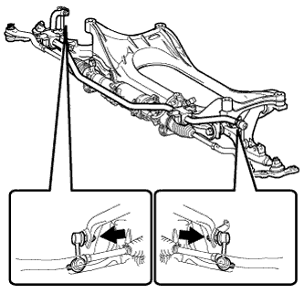
Remove the 2 nuts and the front stabilizer bar.
Tech Tips
If the ball joint turns together with the nut, use a hexagon wrench (6 mm) to hold the stud bolt.
-
-
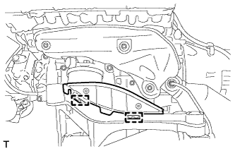
SEPARATE FRONT LOWER SUSPENSION ARM ASSEMBLY LH
-
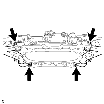
Remove the 4 bolts, washer and separate the front lower suspension arm assembly LH.
-
-
SEPARATE FRONT LOWER SUSPENSION ARM ASSEMBLY RH
Tech Tips
Perform the same procedure as the LH side.
-
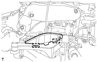
REMOVE POWER STEERING LINK ASSEMBLY
-
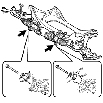
Remove the 2 bolts, 2 washers, 2 nuts, and the power steering link assembly from the front suspension crossmember.
Tech Tips
Remove the power steering link assembly together with the front lower suspension arm assembly.
-