FRONT SHOCK ABSORBER REMOVAL

Tech Tips
-
Use the same procedure for the LH side and RH side.
-
The following procedure listed is for the LH side.
-
REMOVE FRONT WHEEL
-
REMOVE COOL AIR INTAKE DUCT SEAL
-
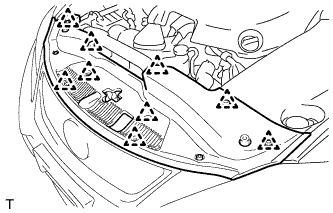
Remove the 9 clips and cool air intake duct seal.
-
-
REMOVE ENGINE ROOM SIDE COVER LH (for LHD)
-

Remove the 5 clips and engine room side cover LH.
-
-
REMOVE ENGINE ROOM SIDE COVER LH (for RHD)
-
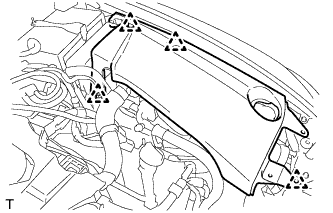
Remove the 4 clips and engine room side cover LH.
-
-
SEPARATE FRONT SPEED SENSOR
-
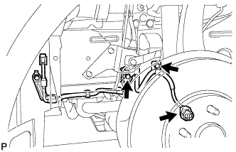
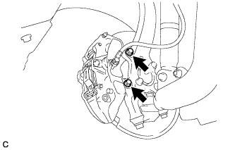
Remove the 2 bolts and separate the front speed sensor from the front shock absorber with coil spring.
Note
Be careful not to deform the bracket of the front shock absorber with coil spring when removing the bolt.
-
Disconnect the front speed sensor connector.
-
-
REMOVE FRONT STABILIZER LINK ASSEMBLY
-
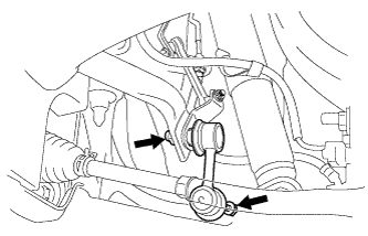
Remove the 2 nuts and the front stabilizer link from the front lower suspension arm.
Tech Tips
If the ball joint turns together with the nut, use a hexagon wrench (6 mm) to hold the stud bolt.
-
-
SEPARATE FRONT DISC BRAKE CYLINDER ASSEMBLY
-
Remove the 2 bolts and separate the front disc brake cylinder assembly.
Note
Use a wire or an equivalent tool to hang the front disc brake cylinder assembly.
-
-
REMOVE FRONT DISC
-
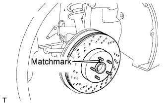
Remove the front disc from the front axle hub.
Tech Tips
Put matchmarks on the disc and axle hub.
-
-
SEPARATE STEERING KNUCKLE WITH AXLE ASSEMBLY
-
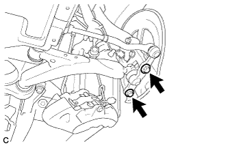
Remove the 2 bolts and separate the steering knuckle with axle assembly.
-
-
REMOVE STEERING KNUCKLE WITH AXLE ASSEMBLY
-
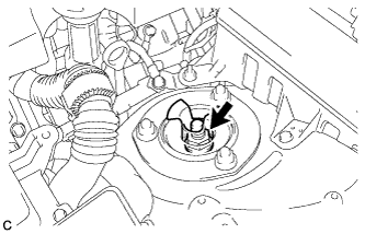
Remove the clip and loosen the nut.
Note
Do not remove the nut.
-
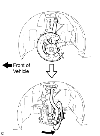
Rotate the steering knuckle as shown in the illustration.
-
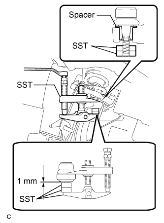
Remove the nut and install 2 spacers (SST spacer B) onto the front upper suspension arm as shown in the illustration.
- SST
- 09960-20010 ( 09961-02060, 09961-02060, 09961-02010 )
Note
As SST may be damaged, make sure that the clearance between the arm and spacers is less than 1 mm (0.0394 in.).
-
Using SST, remove the steering knuckle from the front upper suspension arm as shown in the illustration.
- SST
- 09960-20010 ( 09961-02010 )
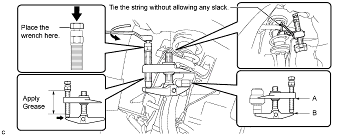
CAUTION:
Apply grease to the threads and end of the SST bolt.
Note
-
Be sure to tighten the string firmly to secure SST to the front upper suspension arm to prevent SST from falling off.
-
Install SST so that A and B are parallel.
-
Be sure to place a wrench on the part indicated in the illustration.
-
Do not damage the front upper suspension arm dust cover.
If the steering knuckle spacer has come off, replace the steering knuckle with a new one.
-
-
SEPARATE FRONT SHOCK ABSORBER WITH COIL SPRING
-
Support the front lower suspension arm with a jack.
Note
Be sure to place a wooden block between the jack and the front lower suspension arm to avoid damage.
-
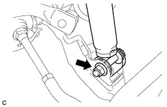
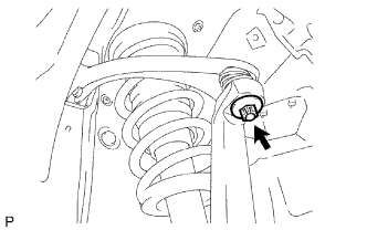
Remove the nut while holding the bolt.
Note
Do not remove the bolt.
-
-
REMOVE FRONT SHOCK ABSORBER WITH COIL SPRING
-
Loosen the lock nut of the front shock absorber.
Note
-
Do not remove the lock nut.
-
Loosen the lock nut only when disassembling the front shock absorber with coil spring.
-
-
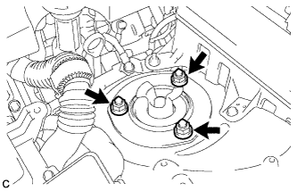
Remove the 3 nuts on the upper side of the front suspension support.
-
Remove the No. 3 front spring support reinforcement.
-
Remove the bolt on the lower side of the front shock absorber.
-
Slowly lower the jack and remove the front shock absorber with coil spring.
-
-
REMOVE FRONT SHOCK ABSORBER
-
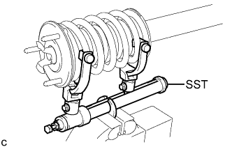
Secure SST in a vise.
- SST
- 09727-30021 ( 09727-00010, 09727-00021, 09727-00031 )
-
Attach the arm of SST to the diameter of the front coil spring.
CAUTION:
-
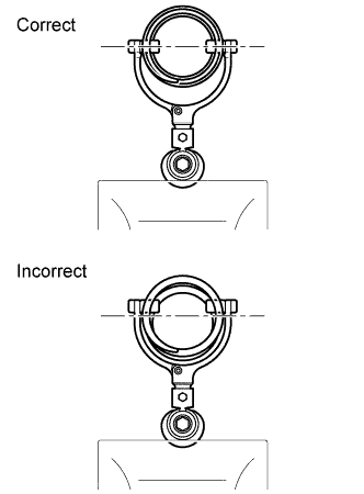
Make sure that the front coil spring is installed so that the distance between the upper and lower hooks of SST is at the maximum.
-
Make sure that the claws of the hooks are securely attached.
-
-
Using SST, compress the front coil spring.
CAUTION:
-
If the front coil spring bends during the compression, immediately stop the compression and reinstall SST.
-
Do not compress the spring until the coil springs contact each other.
-
Do not use an impact wrench.
-
-
Confirm that the front coil spring becomes free and remove the lock nut.
CAUTION:
Do not remove the lock nut when the front coil spring is not free.
-
Remove the front actuator support bracket.
-
Remove the front suspension support assembly with the front upper coil spring insulator.
-
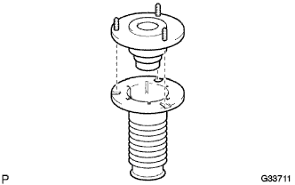
Remove the front upper coil spring insulator from the front suspension support assembly.
-
Remove the front spring bumper from the front suspension support assembly.
-
Remove the front coil spring and SST.
-
Remove the SST from the coil spring.
Note
Do not use an impact wrench. It will damage the SST.
-
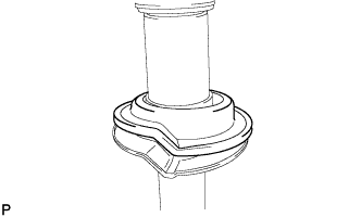
Remove the front lower coil spring insulator.
-