REAR DIFFERENTIAL CARRIER ASSEMBLY INSTALLATION

-
INSTALL REAR DIFFERENTIAL CARRIER ASSEMBLY
Note
When temporarily installing the rear differential carrier assembly and fully tightening its bolts, do not misalign the differential mount cushion bolt holes or rear differential carrier assembly bolts.
-
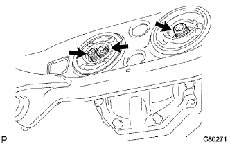
Install the 2 upper rear differential mount stoppers to the rear differential carrier assembly.
-
Support the rear differential carrier assembly with a jack.
Note
Do not drop the differential carrier.
-
Using a hexagon wrench (12 mm), temporarily install the rear differential carrier assembly to the suspension member with 3 new bolts.
-
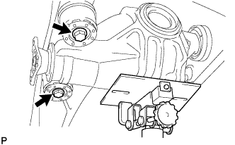
Temporarily install the rear differential carrier assembly to the suspension member with 2 new bolts and 2 lower rear differential mount stoppers.
-
Using a hexagon wrench (12 mm) and torque wrench, tighten the 3 bolts to the specified torque.
- Torque:
- 103 N*m { 1050 kgf*cm, 76 ft.*lbf }
-
Using a torque wrench, tighten the 2 bolts to the specified torque.
- Torque:
- 95 N*m { 970 kgf*cm, 70 ft.*lbf }
Note
-
Make sure to tighten the bolts after checking that the upper rear differential mount stopper and lower rear differential mount stopper are not misaligned or inclined.
-
Do not tilt the inner sleeve or distort rubber parts when fully tightening the differential mount stopper.
-
-
INSTALL REAR STABILIZER BAR
-
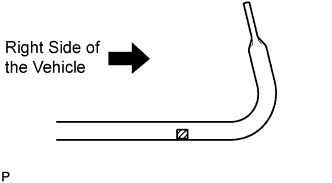
Insert the rear stabilizer bar between the rear suspension member and exhaust tail pipe assembly so that the indication mark on the rear stabilizer bar is on the right of the vehicle.
-
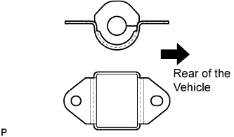
Install the 2 rear stabilizer bushings and the 2 rear stabilizer brackets.
Note
Be sure to install the rear stabilizer bushings so that each cutout faces the rear of the vehicle.
-
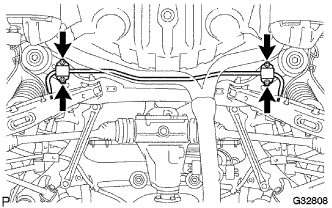
Install the rear stabilizer bar with the 4 bolts.
- Torque:
- 32 N*m { 326 kgf*cm, 24 ft.*lbf }
-
-
INSTALL HOLE SNAP RING
-
Install a new hole snap ring.
-
-
INSTALL REAR DRIVE SHAFT ASSEMBLY LH
-
Coat the spline of the inboard joint shaft assembly with gear oil.
-
Set the shaft snap ring with the opening side facing down.
-
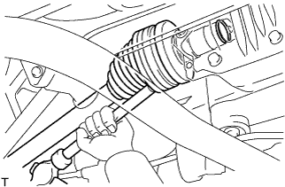
Align the shaft splines and install the drive shaft assembly with a brass bar and a hammer.
Note
-
Be careful not to damage the drive shaft dust cover, boot or oil seal.
-
Move the drive shaft assembly while keeping it level.
Tech Tips
It is possible to determine if the inboard joint shaft is properly engaged (the shaft is in contact with the pinion shaft, and the snap ring is engaged in the pinion gear) based on the sound or feeling when the shaft is driven in.
-
-
Install the rear drive shaft assembly to the rear axle carrier.
Note
Be careful not to damage the drive shaft boot.
-
-
INSTALL REAR DRIVE SHAFT ASSEMBLY RH
Tech Tips
Perform the same procedure as the LH side.
-
INSTALL REAR AXLE ASSEMBLY LH
-
Connect the rear drive shaft assembly and to the rear axle assembly.
-
-
INSTALL REAR AXLE ASSEMBLY RH
Tech Tips
Perform the same procedure as the LH side.
-
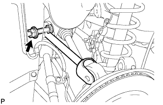
TEMPORARILY TIGHTEN REAR NO. 2 SUSPENSION ARM ASSEMBLY LH
-
Temporarily tighten the rear No. 2 suspension arm assembly to the rear axle carrier sub-assembly with the bolt and nut.
Note
Turn the bolt while holding the nut.
Tech Tips
Install the bolt from the rear side of the vehicle and temporarily tighten the bolt.
-
-
TEMPORARILY TIGHTEN REAR NO. 2 SUSPENSION ARM ASSEMBLY RH
Tech Tips
Perform the same procedure as the LH side.
-
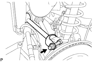
TEMPORARILY TIGHTEN REAR STABILIZER LINK ASSEMBLY LH
-
Temporarily install the stabilizer link assembly and the height control sensor link bracket to the rear No. 2 suspension arm assembly with the bolt and nut.
Tech Tips
Fully tighten the nut after stabilizing the suspension.
-
-
TEMPORARILY TIGHTEN REAR STABILIZER LINK ASSEMBLY RH
Tech Tips
Perform the same procedure as the LH side.
-
TEMPORARILY TIGHTEN REAR NO. 1 UPPER CONTROL ARM ASSEMBLY (for LH Side)
-
Temporarily tighten the rear No. 1 upper control arm assembly to the rear suspension member with the bolt, nut, and washer.
-
Temporarily tighten the rear No. 1 upper control arm assembly to the rear axle carrier sub-assembly with the bolt, nut, and washer.
-
-
TEMPORARILY TIGHTEN REAR NO. 1 UPPER CONTROL ARM ASSEMBLY (for RH Side)
Tech Tips
Perform the same procedure as the LH side.
-
TEMPORARILY TIGHTEN REAR NO. 2 UPPER CONTROL ARM ASSEMBLY (for LH Side)
-
Insert the stud of the rear No. 2 upper control arm assembly to the rear axle carrier sub-assembly.
-
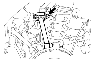
Temporarily install the rear No. 2 upper control arm assembly to the rear suspension member with the bolt, nut, and washer.
Tech Tips
Push the axle carrier downward.
-
Temporarily tighten the nut.
-
Install a new nut and fully tighten the nut.
- Torque:
- 70 N*m { 714 kgf*cm, 52 ft.*lbf }
-
-
TEMPORARILY TIGHTEN REAR NO. 2 UPPER CONTROL ARM ASSEMBLY (for RH Side)
Tech Tips
Perform the same procedure as the LH side.
-
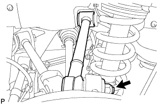
TEMPORARILY TIGHTEN TOE CONTROL LINK SUB-ASSEMBLY LH
-
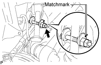
Install the toe control link sub-assembly and insert the toe adjust cam from the front of the vehicle. Then, install the toe adjust plate and temporarily tighten the nut.
Note
Align the matchmarks on the rear suspension member and toe adjust plate.
Tech Tips
Fully tighten the nut after stabilizing the suspension.
-
Install the toe control link sub-assembly with a new nut.
- Torque:
- 70 N*m { 714 kgf*cm, 52 ft.*lbf }
-
-
TEMPORARILY TIGHTEN TOE CONTROL LINK SUB-ASSEMBLY RH
Tech Tips
Perform the same procedure as the LH side.
-
TEMPORARILY TIGHTEN REAR NO. 1 SUSPENSION ARM ASSEMBLY LH
-
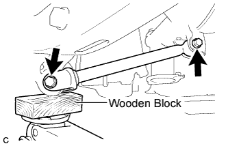
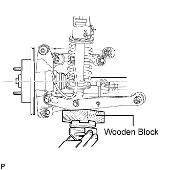
Support the rear axle assembly with a jack using a wooden block.
-
Temporarily tighten the rear No. 1 suspension arm assembly with the 2 bolts and 2 nuts.
Note
Turn the bolts while holding the nuts.
Tech Tips
Fully tighten the bolts after stabilizing the suspension.
-
-
TEMPORARILY TIGHTEN REAR NO. 1 SUSPENSION ARM ASSEMBLY RH
Tech Tips
Perform the same procedure as the LH side.
-
INSTALL NO. 3 PARKING BRAKE CABLE ASSEMBLY
-
Connect the No. 3 parking brake cable assembly to the parking brake equalizer.
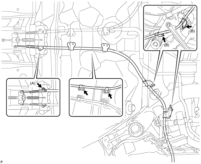
-
Install the No. 3 parking brake cable assembly to the body with the 3 bolts and 2 clamps.
- Torque:
- Bolt (A)
- 6.0 N*m { 61 kgf*cm, 53 in.*lbf }
- Bolt (B)
- 19 N*m { 194 kgf*cm, 14 ft.*lbf }
-
-
INSTALL NO. 2 PARKING BRAKE CABLE ASSEMBLY
Tech Tips
Perform the same procedure as the No. 3 parking brake cable assembly.
-
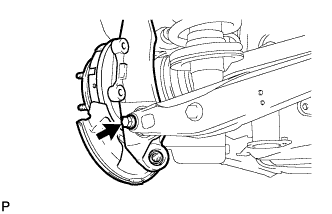
INSTALL REAR SPEED SENSOR LH
-
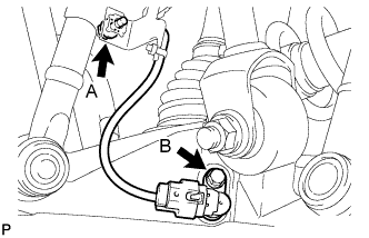
Install the rear speed sensor with the bolt A and bolt B.
- Torque:
- Bolt A
- 6.0 N*m { 61 kgf*cm, 53 in.*lbf }
- Bolt B
- 8.5 N*m { 87 kgf*cm, 75 in.*lbf }
Note
-
Prevent foreign matter from attaching to the sensor tip.
-
Do not twist the rear speed sensor when installing it.
-
-
INSTALL REAR SPEED SENSOR RH
Tech Tips
Perform the same procedure as the LH side.
-
INSTALL REAR DISC (for LH Side)
-
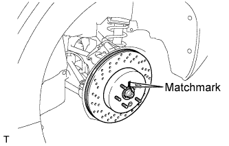
Align matchmarks of the rear disc and rear axle hub, and install the rear disc.
Note
When replacing the disc with a new one, select the installation position where the rear disc has minimal runout.
-
-
INSTALL REAR DISC (for RH Side)
Tech Tips
Perform the same procedure as the LH side.
-
INSTALL REAR DISC BRAKE CYLINDER ASSEMBLY LH
-
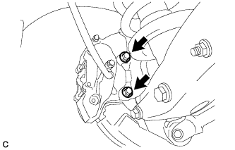
Install the rear disc brake cylinder assembly to the rear axle carrier with the 2 bolts.
- Torque:
- 54 N*m { 551 kgf*cm, 40 ft.*lbf }
Note
-
Do not twist the brake hose.
-
Make sure that the bolts are free from damage and foreign matter.
-
Do not overtighten the bolts.
-
-
INSTALL REAR DISC BRAKE CYLINDER ASSEMBLY RH
Tech Tips
Perform the same procedure as the LH side.
-
INSTALL REAR AXLE SHAFT NUT LH
-
Clean the threaded parts on the drive shaft and axle hub nut using a non-residue solvent.
Note
-
Be sure to perform this work for a new drive shaft.
-
Keep the threaded parts free of oil and foreign objects.
-
-
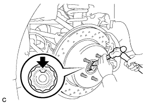
Install a new rear axle shaft nut.
- Torque:
- 290 N*m { 2957 kgf*cm, 214 ft.*lbf }
-
Using a chisel and hammer, stake the rear axle shaft nut.
-
-
INSTALL REAR AXLE SHAFT NUT RH
Tech Tips
Perform the same procedure as the LH side.
-
INSTALL PROPELLER SHAFT WITH CENTER BEARING ASSEMBLY
-
Install the propeller shaft with center bearing assembly Click here.
-
-
STABILIZE SUSPENSION
-
Install the rear wheels.
-
Lower the vehicle to the ground.
-
Bounce the vehicle up and down at the corners to stabilize the rear suspension.
-
Remove the rear wheels.
-
Jack up the axle carrier, with a wooden block placed between the jack and axle carrier, to apply a load to the suspension so that the rear drive shaft assembly becomes level.
-
-
FULLY TIGHTEN TOE CONTROL LINK SUB-ASSEMBLY LH
-
Fully tighten the nut on the rear suspension member side.
- Torque:
- 50 N*m { 510 kgf*cm, 37 ft.*lbf }
Note
Check that the matchmarks on the rear suspension member and toe adjust plate are aligned.
-
-
FULLY TIGHTEN TOE CONTROL LINK SUB-ASSEMBLY RH
Tech Tips
Perform the same procedure as the LH side.
-
FULLY TIGHTEN REAR NO. 1 UPPER CONTROL ARM ASSEMBLY (for LH Side)
-

Fully tighten the nut.
- Torque:
- 161 N*m { 1642 kgf*cm, 119 ft.*lbf }
-
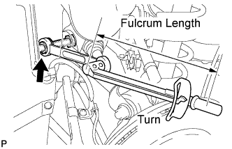
Using a ball joint lock nut wrench (19 mm), fully tighten the nut.
- Torque:
- without the ball joint lock nut wrench (19 mm)
- 161 N*m { 1642 kgf*cm, 119 ft.*lbf }
- with the ball joint lock nut wrench (19 mm)
- 119 N*m { 1214 kgf*cm, 88 ft.*lbf }
Note
-
Use a torque wrench with a fulcrum length of 425 mm (16.73 in.).
-
Use the recommended ball joint lock nut wrench (19 mm).
-
This torque value is effective when the ball joint lock nut wrench (19 mm) is parallel to the torque wrench.
-
-
FULLY TIGHTEN REAR NO. 1 UPPER CONTROL ARM ASSEMBLY (for RH Side)
Tech Tips
Perform the same procedure as the LH side.
-
FULLY TIGHTEN REAR NO. 2 UPPER CONTROL ARM ASSEMBLY (for LH Side)
-
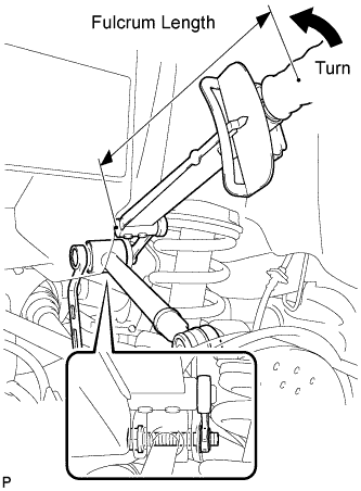
Using a ball joint lock nut wrench (19 mm), fully tighten the nut.
- Torque:
- without the ball joint lock nut wrench (19 mm)
- 145 N*m { 1479 kgf*cm, 107 ft.*lbf }
- with the ball joint lock nut wrench (19 mm)
- 107 N*m { 1091 kgf*cm, 79 ft.*lbf }
Note
-
Use a torque wrench with a fulcrum length of 425 mm (16.73 in.).
-
Use the recommended ball joint lock nut wrench (19 mm).
-
This torque value is effective when the ball joint lock nut wrench (19 mm) is parallel to the torque wrench.
-
-
FULLY TIGHTEN REAR NO. 2 UPPER CONTROL ARM ASSEMBLY (for RH Side)
Tech Tips
Perform the same procedure as the LH side.
-
FULLY TIGHTEN REAR NO. 1 SUSPENSION ARM ASSEMBLY LH
-

Fully tighten the 2 bolts.
- Torque:
- Bolt A
- 95 N*m { 969 kgf*cm, 70 ft.*lbf }
- Bolt B
- 100 N*m { 1020 kgf*cm, 74 ft.*lbf }
Note
Turn the bolts while holding the nuts.
-
-
FULLY TIGHTEN REAR NO. 1 SUSPENSION ARM ASSEMBLY RH
Tech Tips
Perform the same procedure as the LH side.
-
FULLY TIGHTEN REAR NO. 2 SUSPENSION ARM ASSEMBLY LH
-
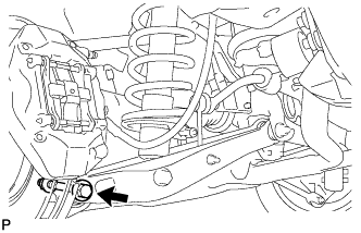
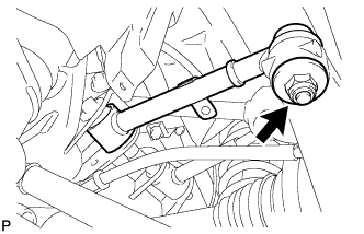
Fully tighten the rear No. 2 suspension arm assembly with the bolt and nut.
- Torque:
- 161 N*m { 1642 kgf*cm, 119 ft.*lbf }
Note
Turn the bolt while holding the nut.
-
-
FULLY TIGHTEN REAR NO. 2 SUSPENSION ARM ASSEMBLY RH
Tech Tips
Perform the same procedure as the LH side.
-
FULLY TIGHTEN REAR STABILIZER LINK ASSEMBLY LH
-
Fully tighten the nut.
- Torque:
- 27 N*m { 275 kgf*cm, 20 ft.*lbf }
-
-
FULLY TIGHTEN REAR STABILIZER LINK ASSEMBLY RH
Tech Tips
Perform the same procedure as the LH side.
-
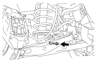
FULLY TIGHTEN REAR SHOCK ABSORBER BOLT (for LH Side)
-
Fully tighten the bolt.
- Torque:
- 110 N*m { 1122 kgf*cm, 81 ft.*lbf }
Note
Turn the bolt while holding the nut.
-
-
FULLY TIGHTEN REAR SHOCK ABSORBER BOLT (for RH Side)
Tech Tips
Perform the same procedure as the LH side.
-
INSTALL REAR SUSPENSION MEMBER BRACE LH
-
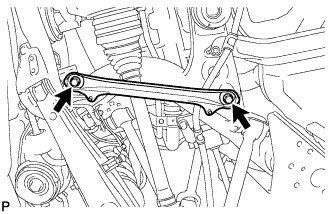
Install the rear suspension member brace with the 2 bolts.
- Torque:
- 50 N*m { 510 kgf*cm, 37 ft.*lbf }
-
-
INSTALL REAR SUSPENSION MEMBER BRACE RH
Tech Tips
Perform the same procedure as the LH side.
-
INSTALL NO. 2 DIFFERENTIAL SUPPORT PROTECTOR
-
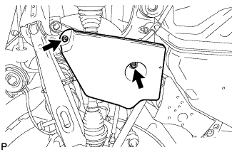
Install the No. 2 differential support protector with the 2 nuts.
-
-
INSTALL NO. 1 DIFFERENTIAL SUPPORT PROTECTOR
Tech Tips
Perform the same procedure as the No. 2 differential support protector.
-
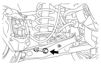
ADD DIFFERENTIAL OIL
-
Using a hexagon wrench (10 mm), remove the differential filler plug and gasket.
-
Add oil.
Capacity 1.3 to 1.4 liters (1.4 to 1.5 US qts, 1.1 to 1.2 Imp. qts) Oil grade Toyota genuine differential gear oil LX 75W-85 GL-5 or equivalent -
Check the oil level.
-
Using a hexagon wrench (10 mm), install the differential filler plug with a new gasket.
- Torque:
- 49 N*m { 500 kgf*cm, 36 ft.*lbf }
Note
After replacing the oil, recheck the oil level after driving.
-
-
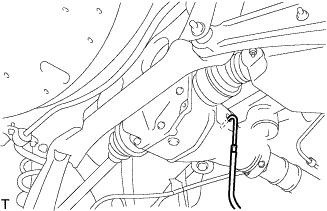
INSPECT FOR DIFFERENTIAL OIL LEAK
-
INSTALL REAR WHEELS
- Torque:
- 103 N*m { 1050 kgf*cm, 76 ft.*lbf }
-
INSPECT AND ADJUST REAR WHEEL ALIGNMENT
-
CHECK ABS SPEED SENSOR SIGNAL
-
INSPECT AND ADJUST HEADLIGHT AIMING
-
INSPECT AND ADJUST FOG LIGHT AIMING