FRONT UPPER SUSPENSION ARM INSTALLATION

Tech Tips
-
Use the same procedure for the LH side and RH side.
-
The following procedure listed is for the LH side.
-
INSTALL FRONT UPPER SUSPENSION ARM ASSEMBLY
-
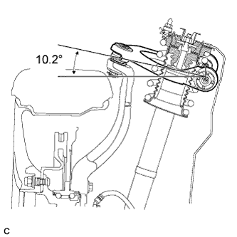
Temporarily install the front upper suspension arm assembly with the 2 bolts.
Tech Tips
When installing the front upper suspension arm assembly, temporarily tighten the bolts at the position shown in the illustration.
-

Fully tighten the front upper suspension arm assembly with the 2 bolts.
- Torque:
- 49 N*m { 500 kgf*cm, 36 ft.*lbf }
-
-
TEMPORARILY TIGHTEN FRONT SHOCK ABSORBER WITH COIL SPRING
-
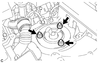
Install the front shock absorber with front coil spring and front No. 3 spring support reinforcement on the vehicle by tightening the 3 nuts on the suspension support side.
- Torque:
- 67 N*m { 683 kgf*cm, 49 ft.*lbf }
-
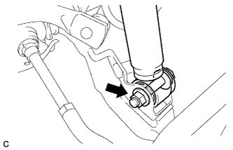
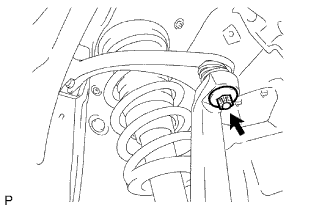
Insert the bolt from the rear of the vehicle, and install the front shock absorber lower side on the front lower suspension arm.
-
Temporarily tighten the nut while holding the bolt.
Tech Tips
Fully tighten the nut after stabilizing the suspension.
-
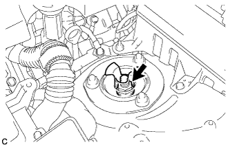
Tighten a new lock nut.
- Torque:
- 28 N*m { 286 kgf*cm, 21 ft.*lbf }
-
-
INSTALL FRONT UPPER SUSPENSION ARM ASSEMBLY
-
Install the steering knuckle to the front upper suspension arm assembly, and install them with the nut.
- Torque:
- 87 N*m { 887 kgf*cm, 64 ft.*lbf }
-
Install a new clip to the steering knuckle.
Note
-
Further tighten the nut up to 60° if the holes for the clip are not aligned.
-
Do not loosen the nut to align the holes for the clip.
-
-
-
INSTALL STEERING KNUCKLE WITH AXLE ASSEMBLY
-
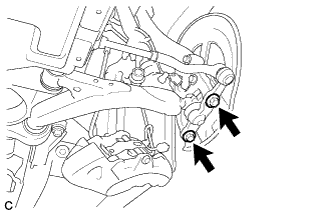
Install the steering knuckle with axle assembly to the front lower ball joint assembly with the 2 bolts.
- Torque:
- 120 N*m { 1223 kgf*cm, 89 ft.*lbf }
-
-
INSTALL FRONT DISC
-
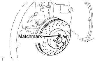
Align the matchmarks of the disc and axle hub, and install the front disc.
Note
When replacing the disc with a new one, select the installation position where the front disc has minimal runout.
-
-
INSTALL FRONT DISC BRAKE CYLINDER ASSEMBLY
-
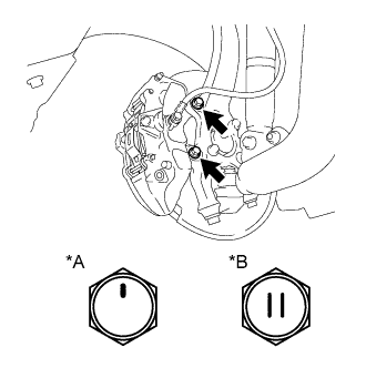
Text in Illustration *A for Bolt A *B for Bolt B Install the front disc brake cylinder assembly with the 2 bolts.
- Torque:
- for Bolt A
- 78 N*m { 799 kgf*cm, 58 ft.*lbf }
- for Bolt B
- 135 N*m { 1377 kgf*cm, 100 ft.*lbf }
Note
Do not twist the brake hose when installing the front disc brake cylinder assembly.
-
-
CONNECT FRONT SPEED SENSOR
-
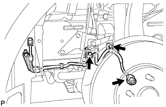
Connect the front speed sensor to the front shock absorber with coil spring with the 2 bolts.
- Torque:
- 6.0 N*m { 61 kgf*cm, 53 in.*lbf }
Note
-
Do not twist the front speed sensor while installing it.
-
Be careful not to deform the bracket of the front shock absorber with coil spring when installing the bolts.
-
Connect the front speed sensor connector.
-
-
INSTALL FRONT STABILIZER LINK ASSEMBLY
-
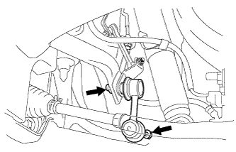
Install the front stabilizer link assembly with the 2 nuts.
- Torque:
- 84 N*m { 857 kgf*cm, 62 ft.*lbf }
Tech Tips
If the ball joint turns together with the nut, use a hexagon wrench (6 mm) to hold the stud bolt.
-
-
STABILIZE SUSPENSION
-
Install the front wheel.
- Torque:
- 103 N*m { 1050 kgf*cm, 76 ft.*lbf }
-
Lower the vehicle and bounce it up and down several times to stabilize the front suspension. Raise the vehicle.
-
Remove the front wheel.
-
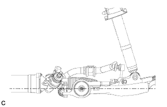
Jack up the front lower suspension arm placing a wooden block in between. Apply a load to the front suspension so that the front lower suspension arm is placed in a horizontal position.
-
-
FULLY TIGHTEN FRONT SHOCK ABSORBER WITH COIL SPRING
-
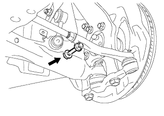
Fully tighten the bolt on the lower side of the front shock absorber while holding the nut.
- Torque:
- 157 N*m { 1601 kgf*cm, 116 ft.*lbf }
-
-
INSTALL ENGINE ROOM SIDE COVER LH (for RHD)
-
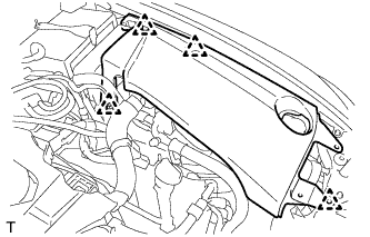
Install the engine room side cover LH with the 4 clips.
-
-
INSTALL ENGINE ROOM SIDE COVER LH (for LHD)
-

Install the engine room side cover LH with the 5 clips.
-
-
INSTALL COOL AIR INTAKE DUCT SEAL
-
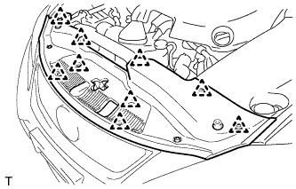
Install the cool air intake duct seal with the 9 clips.
-
-
INSTALL FRONT WHEEL
- Torque:
- 103 N*m { 1050 kgf*cm, 76 ft.*lbf }
-
CHECK FOR SPEED SENSOR SIGNAL
Tech Tips
Check for speed sensor signal. Click here
-
INSPECT AND ADJUST FRONT WHEEL ALIGNMENT
Tech Tips
Inspect and adjust front wheel alignment. Click here