REAR DIFFERENTIAL CARRIER ASSEMBLY REMOVAL

-
REMOVE REAR WHEELS
-
DRAIN DIFFERENTIAL OIL
-
Using a hexagon wrench (10 mm), remove the differential filler plug and gasket.
-
Using a hexagon wrench (10 mm), remove the differential drain plug and gasket, and drain the oil.
-
-
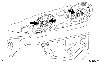
REMOVE NO. 2 DIFFERENTIAL SUPPORT PROTECTOR
-
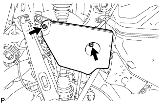
Remove the 2 nuts and No. 2 differential support protector.
-
-
REMOVE NO. 1 DIFFERENTIAL SUPPORT PROTECTOR
Tech Tips
Perform the same procedure as the No. 2 differential support protector.
-
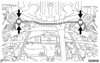
REMOVE REAR SUSPENSION MEMBER BRACE LH
-
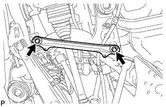
Remove the 2 bolts and rear suspension member brace.
-
-
REMOVE REAR SUSPENSION MEMBER BRACE RH
Tech Tips
Perform the same procedure as the LH side.
-
REMOVE PROPELLER SHAFT WITH CENTER BEARING ASSEMBLY
-
REMOVE REAR AXLE SHAFT NUT LH
-
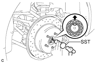
Using SST and a hammer, release the staked part of the axle shaft nut.
- SST
- 09930-00010
Note
Release the staked part of the nut completely, otherwise the threads of the drive shaft may be damaged.
-
While depressing the brake pedal, remove the axle shaft nut.
-
-
REMOVE REAR AXLE SHAFT NUT RH
Tech Tips
Perform the same procedure as the LH side.
-
SEPARATE REAR DISC BRAKE CYLINDER ASSEMBLY LH
-
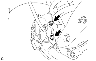
Remove the 2 bolts and separate the rear disc brake cylinder assembly.
Note
Hang the caliper with wire or equivalent.
-
-
SEPARATE REAR DISC BRAKE CYLINDER ASSEMBLY RH
Tech Tips
Perform the same procedure as the LH side.
-
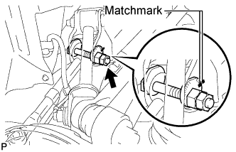
REMOVE REAR DISC (for LH Side)
-
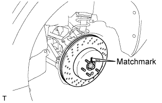
Put matchmarks on the rear disc and rear axle hub.
-
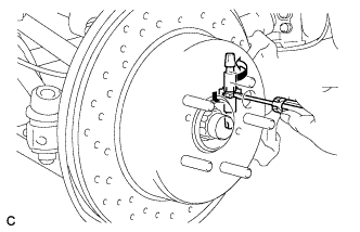
Release the parking brake and remove the rear disc.
Tech Tips
If the disc cannot be removed easily, turn and press firmly the shoe adjuster until the wheel comes free.
-
-
REMOVE REAR DISC (for RH Side)
Tech Tips
Perform the same procedure as the LH side.
-
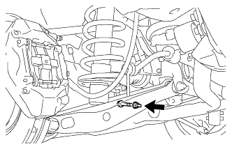
SEPARATE REAR SPEED SENSOR LH
-
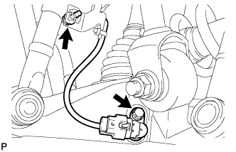
Remove the 2 bolts and separate the rear speed sensor.
Note
Prevent foreign matter from attaching to the sensor tip.
-
-
SEPARATE REAR SPEED SENSOR RH
Tech Tips
Perform the same procedure as the LH side.
-
SEPARATE NO. 3 PARKING BRAKE CABLE ASSEMBLY
-
Remove the 3 bolts and disengage the 2 clamps.
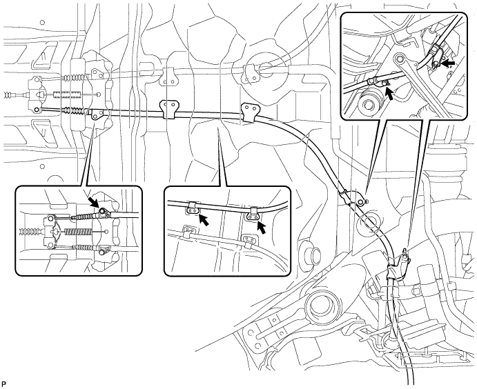
-
Separate the No. 3 parking brake cable assembly from the parking brake equalizer.
-
-
SEPARATE NO. 2 PARKING BRAKE CABLE ASSEMBLY
Tech Tips
Perform the same procedure as the No. 3 parking brake cable assembly.
-
REMOVE REAR NO. 1 SUSPENSION ARM ASSEMBLY LH
-
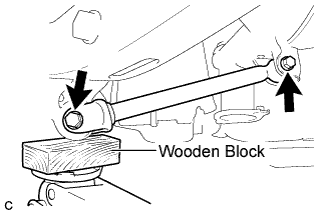
Support the rear axle assembly with a jack using a wooden block.
-
Remove the 2 bolts, 2 nuts, and rear No. 1 suspension arm assembly.
Note
Turn the bolts while holding the nuts.
-
-
REMOVE REAR NO. 1 SUSPENSION ARM ASSEMBLY RH
Tech Tips
Perform the same procedure as the LH side.
-
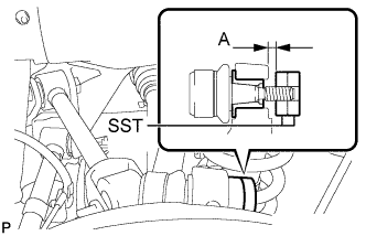
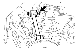
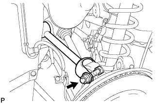
REMOVE TOE CONTROL LINK SUB-ASSEMBLY LH
-
Remove the nut.
-
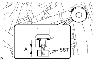
Install 2 spacers (SST spacer B) as shown in the illustration.
- SST
- 09960-20010 ( 09961-02060, 09961-02060 )
A 1 mm (0.0394 in.) or more Note
As SST may be damaged, make sure that the clearance between the arm and spacers is less than 1 mm (0.0394 in.).
-
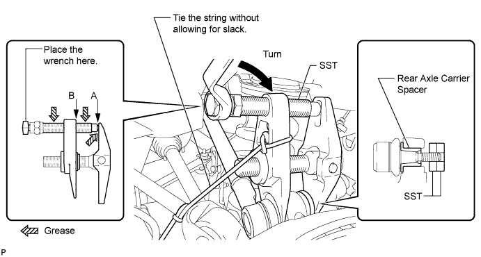
Using SST, remove the toe control link sub-assembly from the rear axle carrier sub-assembly as shown in the illustration.
- SST
- 09960-20010 ( 09961-02010, 09961-02060, 09961-02060 )
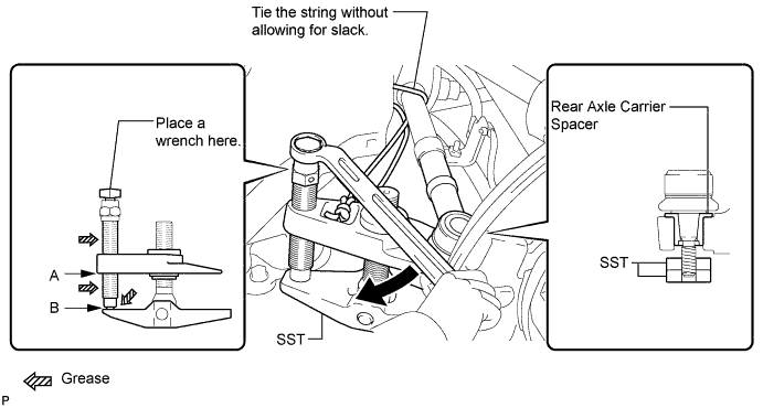
CAUTION:
Apply grease to the threads and end of the SST bolt.
Note
-
Install SST so that A and B are parallel.
-
Be sure to place a wrench on the part indicated in the illustration.
-
Make sure that SST is securely positioned on the rear axle carrier spacer.
-
Use caution not to damage the rear axle carrier sub-assembly because it is made of aluminum and may be damaged easily.
-
Do not damage the ball joint dust cover.
-
Make sure that the SST string is securely tied to the vehicle.
If the rear axle carrier spacer has come off, replace the rear axle carrier sub-assembly with a new one.
-
Put matchmarks on the toe adjust plate and rear suspension member.
-
Remove the nut, toe adjust cam, toe adjust plate, and toe control link sub-assembly.
-
-
REMOVE TOE CONTROL LINK SUB-ASSEMBLY RH
Tech Tips
Perform the same procedure as the LH side.
-
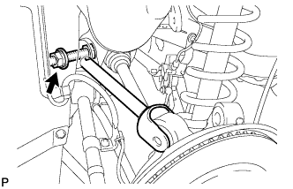
REMOVE REAR NO. 2 UPPER CONTROL ARM ASSEMBLY (for LH Side)
-
Remove the nut.
-
Install 2 spacers (SST spacer B) as shown in the illustration.
- SST
- 09960-20010 ( 09961-02060, 09961-02060 )
A 1 mm (0.0394 in.) or more Note
As SST may be damaged, make sure that the clearance between the arm and spacers is less than 1 mm (0.0394 in.).
-
Using SST, separate the rear No. 2 upper control arm assembly from the rear axle carrier sub-assembly as shown in the illustration.
- SST
- 09960-20010 ( 09961-02010, 09961-02060, 09961-02060 )
CAUTION:
Apply grease to the threads and end of the SST bolt.
Note
-
Install SST so that A and B are parallel.
-
Be sure to place a wrench on the part indicated in the illustration.
-
Make sure that SST is securely positioned on the rear axle carrier.
-
Use caution not to damage the rear axle carrier sub-assembly because it is made of aluminum and may be damaged easily.
-
Do not damage the ball joint dust cover.
-
Make sure that the SST string is securely tied to the vehicle.
If the rear axle carrier spacer has come off, replace the rear axle carrier sub-assembly with a new one.
-
Remove the bolt, nut, washer, and rear No. 2 upper control arm assembly.
Tech Tips
Push the rear axle assembly downward.
-
-
REMOVE REAR NO. 2 UPPER CONTROL ARM ASSEMBLY (for RH Side)
Tech Tips
Perform the same procedure as the LH side.
-
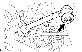
REMOVE REAR NO. 1 UPPER CONTROL ARM ASSEMBLY (for LH Side)
-
Remove the bolt, nut, and washer, and separate the rear No. 1 upper control arm assembly from the rear axle carrier.
-
Remove the bolt, nut, washer, and rear No. 1 upper control arm assembly.
-
-
REMOVE REAR NO. 1 UPPER CONTROL ARM ASSEMBLY (for RH Side)
Tech Tips
Perform the same procedure as the LH side.
-
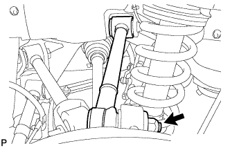
LOOSEN REAR SHOCK ABSORBER BOLT (for LH Side)
-
Loosen the bolt.
Note
-
Do not remove the bolt.
-
Turn the bolt while holding the nut.
-
-
-
LOOSEN REAR SHOCK ABSORBER BOLT (for RH Side)
Tech Tips
Perform the same procedure as the LH side.
-
SEPARATE REAR STABILIZER LINK ASSEMBLY LH
-
Remove the nut and bolt, and separate the rear stabilizer link assembly and the height control sensor link bracket from the rear No. 2 suspension arm.
-
-
SEPARATE REAR STABILIZER LINK ASSEMBLY RH
Tech Tips
Perform the same procedure as the LH side.
-
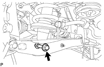
SEPARATE REAR NO. 2 SUSPENSION ARM ASSEMBLY LH
-
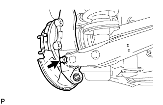
Remove the bolt and nut, and separate the rear No. 2 suspension arm assembly from the rear axle carrier sub-assembly.
Note
Turn the bolt while holding the nut.
-
-
SEPARATE REAR NO. 2 SUSPENSION ARM ASSEMBLY RH
Tech Tips
Perform the same procedure as the LH side.
-
REMOVE REAR AXLE ASSEMBLY LH
-
Using a plastic hammer, separate the rear drive shaft assembly from the rear axle assembly.
Note
-
Be careful not to damage the boot.
-
Use wire or equivalent to prevent the rear drive shaft assembly from hanging down.
-
-
-
REMOVE REAR AXLE ASSEMBLY RH
Tech Tips
Perform the same procedure as the LH side.
-
REMOVE REAR DRIVE SHAFT ASSEMBLY LH
-
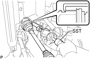
Using SST, remove the rear drive shaft assembly.
- SST
- 09520-01010
- 09520-24010 ( 09520-32040 )
Note
-
Be careful not to damage the oil seal, inboard joint boot or drive shaft dust cover.
-
Be careful not to drop the drive shaft assembly.
-
-
REMOVE REAR DRIVE SHAFT ASSEMBLY RH
Tech Tips
Perform the same procedure as the LH side.
-
REMOVE HOLE SNAP RING
-
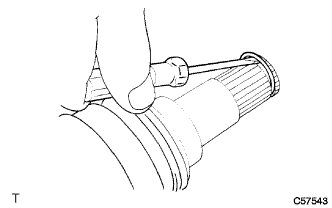
Using a screwdriver, remove the hole snap ring.
-
-
REMOVE REAR STABILIZER BAR
-
Remove the 4 bolts, 2 stabilizer brackets, 2 rear stabilizer bushings, and rear stabilizer bar.
-
-
REMOVE REAR DIFFERENTIAL CARRIER ASSEMBLY
-
Support the rear differential carrier assembly with a jack.
Note
Do not drop the differential carrier.
-
Using a hexagon wrench (12 mm), remove the 3 hexagon bolts.
-
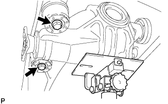
Remove the 2 bolts, 2 lower rear differential mount stoppers and rear differential carrier assembly.
-
Remove the 2 upper rear differential mount stoppers from rear differential carrier assembly
Note
Make sure not to install the upper and lower rear differential mount stoppers upside down.
-