REAR DIFFERENTIAL CARRIER OIL SEAL REPLACEMENT

-
REMOVE REAR DIFFERENTIAL CARRIER ASSEMBLY
-
Remove the rear differential carrier assembly Click here.
-
-
REMOVE REAR DIFFERENTIAL CARRIER COVER
-
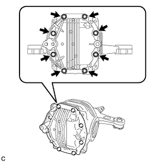
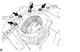
Remove the 8 bolts from the differential carrier cover.
-
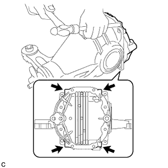
Using a brass bar and a hammer, remove the differential carrier cover from the differential carrier.
Note
-
Place the brass bar onto the corners of the carrier cover.
-
Do not damage the sealing surface of the differential carrier.
-
-
-
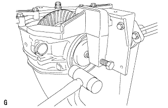
SECURE REAR DIFFERENTIAL CARRIER
-
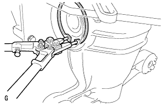
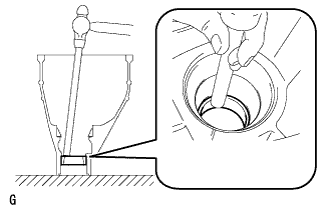
Set the differential carrier to the overhaul stand, etc., as shown in the illustration.
-
-
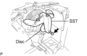
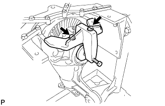
REMOVE REAR DIFFERENTIAL SIDE GEAR SHAFT OIL SEAL
-
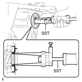
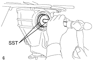
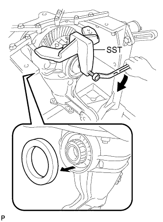
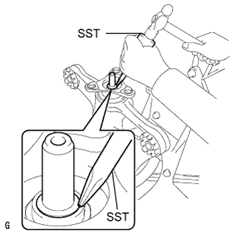
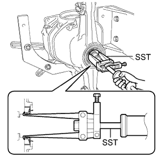
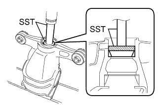
Using SST, remove the 2 rear differential side gear shaft oil seals.
- SST
- 09308-00010
-
-
REMOVE REAR DIFFERENTIAL SIDE GEAR SHAFT SNAP RING (for RH Side)
-
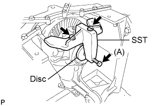
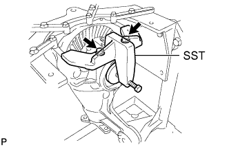
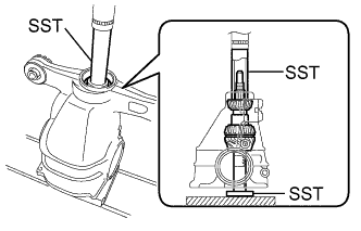
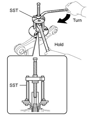
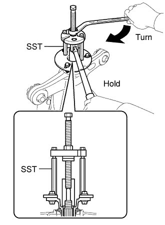
Install SST to the differential carrier.
- SST
- 09571-50010
-
Tighten the SST bolt (A) until the SST disc lightly touches the differential side bearing outer race RH.
-
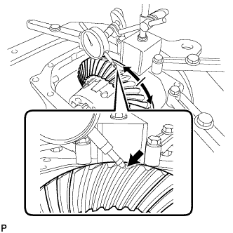
Install a dial indicator to the rear differential carrier.
-
Tighten the SST bolt and alter the shape of the differential carrier to create a 0.1 mm (0.00394 in.) clearance between the differential side bearing outer race RH and side gear shaft snap ring.
Note
Observe the dial indicator to ensure that the clearance does not change more than 0.2 mm (0.00787 in.).
Tech Tips
-
Set the dial indicator to the rearmost position (upper side in the illustration) of the area around where the side gear shaft oil seal is tapped in.
-
Approximately 0.1 mm (0.00394 in.) clearance between the differential side bearing outer race RH and the side gear shaft snap ring is sufficient for the washer to move slightly.
-
-
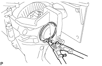
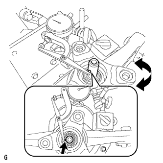
Using snap ring pliers, remove the side gear shaft snap ring on the ring gear tooth side.
Tech Tips
For reassembly purposes, measure the thickness of the side gear shaft snap ring. Write down the result.
-
Remove the dial indicator and loosen the SST bolt.
Note
Do not remove SST.
-
-
REMOVE REAR DIFFERENTIAL SIDE GEAR SHAFT SNAP RING (for LH Side)
-
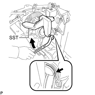
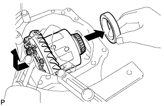
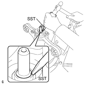
Using SST and a hammer, create a clearance between the differential side bearing outer race LH on the back surface of the ring gear and side gear shaft snap ring.
- SST
- 09608-32010
- 09950-70010 ( 09951-07200 )
Tech Tips
The clearance is not visible, but tapping SST with a hammer three or four times should be enough.
-
Using snap ring pliers, remove the side gear shaft snap ring on the back surface of the ring gear.
Tech Tips
For reassembly purposes, measure the thickness of the side gear shaft snap ring. Write down the result.
-
-
REMOVE DIFFERENTIAL SIDE BEARING OUTER RACE LH
-
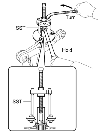
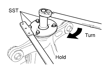
Tighten the SST bolt and push out the differential side bearing outer race LH on the back surface of the ring gear.
- SST
- 09571-50010
Note
Do not drop the differential side bearing outer race LH.
-
Remove the 2 bolts and SST.
-
-
REMOVE DIFFERENTIAL SIDE BEARING OUTER RACE RH
-
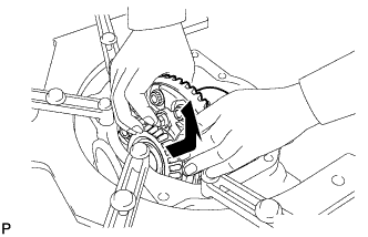
Raise the ring gear of the differential case slightly to remove the ring gear tooth side differential side bearing outer race RH.
Tech Tips
For reassembly purposes, take note of the installation position of the differential side bearing outer race and the side gear shaft snap ring before removing the differential side bearing outer race.
-
-
REMOVE REAR DIFFERENTIAL CASE SUB-ASSEMBLY
-
Remove the rear differential case sub-assembly.
Note
Do not damage the case bearing.
-
-
REMOVE REAR DRIVE PINION NUT
-
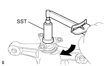
Using SST and a hammer, unstake the staked part of the drive pinion nut.
- SST
- 09930-00010
Note
-
Be sure to use SST with the tapered surface facing the shaft.
-
Do not grind the tip of SST with a grinder, etc.
-
Completely loosen the staked part of the nut when removing it.
-
Do not damage the threads of the drive pinion.
-
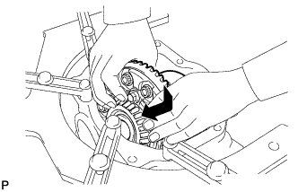
Using SST to hold the flange, remove the drive pinion nut.
- SST
- 09229-55010
- 09330-00021
- 09950-30012 ( 09955-03040 )
-
-
REMOVE REAR DRIVE PINION COMPANION FLANGE
-
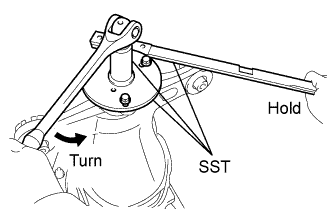
Using SST, remove the companion flange.
- SST
- 09950-30012 ( 09951-03010, 09953-03010, 09954-03010, 09955-03040, 09956-03060 )
Note
Apply grease to the threads and tip of the SST center bolt before use.
-
-
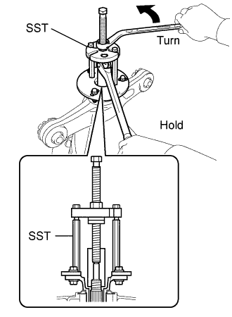
REMOVE REAR DIFFERENTIAL CARRIER OIL SEAL
-
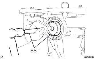
Using SST, remove the rear differential carrier oil seal from the rear differential carrier.
- SST
- 09308-00010
-
-
REMOVE REAR DIFFERENTIAL DRIVE PINION OIL SLINGER
-
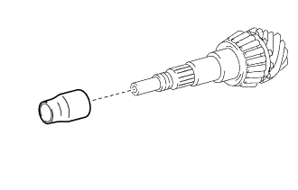
Remove the drive pinion oil slinger.
-
-
REMOVE DIFFERENTIAL DRIVE PINION
-
Using a press, remove the drive pinion from the differential carrier.
Note
Do not drop the drive pinion.
-
-
REMOVE REAR DIFFERENTIAL DRIVE PINION BEARING SPACER
-
Remove the rear differential drive pinion bearing spacer from the differential drive pinion.
-
-
REMOVE REAR DRIVE PINION FRONT TAPERED ROLLER BEARING
-
Remove the rear drive pinion front tapered roller bearing inner race from the differential carrier.
-
Using a brass bar and a hammer, remove the rear drive pinion front tapered roller bearing outer race from the differential carrier.
-
-
INSTALL REAR DRIVE PINION FRONT TAPERED ROLLER BEARING
-
Using SST and a press, install the rear drive pinion front tapered roller bearing outer race.
- SST
- 09950-60020 ( 09951-00710 )
- 09950-70010 ( 09951-07100 )
-
Install the rear drive pinion front tapered roller bearing to the differential carrier.
-
-
INSTALL DIFFERENTIAL DRIVE PINION
-
Using SST and a press, install the differential drive pinion.
- SST
- 09316-60011 ( 09316-00011, 09316-00041 )
- 09608-04031
Tech Tips
Install the rear differential drive pinion bearing spacer and oil seal after adjusting the tooth contact pattern.
-
-
INSTALL REAR DIFFERENTIAL DRIVE PINION OIL SLINGER
-
Install the drive pinion oil slinger.
-
-
ADJUST DIFFERENTIAL DRIVE PINION PRELOAD
-
Using SST, install the companion flange.
- SST
- 09950-30012 ( 09951-03010, 09953-03010, 09954-03010, 09955-03040, 09956-03060 )
Note
-
Install the companion flange so that there is a slight looseness on the drive pinion because the bearing spacer is not yet installed.
-
Apply grease to the threads and tip of the SST center bolt before use.
-
Coat the threads of the drive pinion nut with hypoid gear oil LSD.
-
Using SST to hold the flange, tighten the drive pinion nut.
- SST
- 09229-55010
- 09330-00021
- 09950-30012 ( 09955-03040 )
Tech Tips
Tighten the nut to approximately 100 N*m (1020 kgf*cm, 74 ft.*lbf), and tighten it further while checking the preload.
Note
-
Apply hypoid gear oil LSD to the nut and the threads of the drive pinion.
-
As there is no bearing spacer, tighten the nut a little at a time and do not overtighten it.
-
Turn the bearing clockwise and counterclockwise several times to stabilize it.
-
Using SST and a torque wrench, measure the preload.
- SST
- 09229-55010
Differential drive pinion preload (starting torque) 1.15 to 1.55 N*m (12 to 15 kgf*cm, 11 to 13 in.*lbf) Note
Record the preload for total preload measurement.
If the preload is not within the specified range, adjust the rear differential drive pinion preload or repair as necessary.
-
-
INSTALL REAR DIFFERENTIAL CASE SUB-ASSEMBLY
-
Insert the differential case from the ring gear tooth side to install the differential case.
Note
Do not damage the case bearing and ring gear.
-
-
INSTALL DIFFERENTIAL SIDE BEARING OUTER RACE RH
-
Using SST and a hammer, install the ring gear tooth side differential side bearing outer race RH.
- SST
- 09608-32010
- 09950-70010 ( 09951-07200 )
Tech Tips
Tap in the differential side bearing outer race RH until half of the side gear shaft snap ring groove of the differential carrier can be seen.
-
-
INSTALL DIFFERENTIAL SIDE BEARING OUTER RACE LH
-
Install SST to the differential carrier with the 2 bolts.
- SST
- 09571-50010
-
Tighten the SST bolt (A) until the SST disc lightly touches the differential side bearing outer race LH.
-
Using SST and a hammer, install the ring gear back surface side differential side bearing outer race LH.
- SST
- 09608-32010
- 09950-70010 ( 09951-07200 )
Tech Tips
Tap in the differential side bearing outer race LH until it touches the case bearing inner race roller.
-
-
INSTALL REAR DIFFERENTIAL SIDE GEAR SHAFT SNAP RING
-
Using snap ring pliers, install the thinnest side gear shaft snap ring on the back surface of the ring gear.
Tech Tips
-
If the final gear set (drive pinion and ring gear) and case bearing are new, select a thinner side gear shaft snap ring and install it.
-
If the final gear set (drive pinion and ring gear) and case bearing are reused, install a side gear shaft snap ring with the same thickness as the removed one.
-
-
Install a dial indicator to the differential carrier.
-
Tighten the SST bolt to alter the shape of the differential carrier by approximately 0.1 mm (0.00394 in.).
- SST
- 09571-50010
Note
Observe the dial indicator to ensure that the clearance does not change more than 0.2 mm (0.00787 in.).
Tech Tips
-
Set the dial indicator to the rearmost position (upper side in the illustration) of the area around where the side gear shaft oil seal is tapped in.
-
Tighten the SST bolt to apply the preload to the case bearing.
-
Turn the ring gear clockwise and counterclockwise several times.
-
Using a dial indicator, measure the backlash of the ring gear at 3 positions.
Backlash 0.08 to 0.13 mm (0.00315 to 0.00512 in.) Note
The difference between the maximum and minimum values must be within 0.05 mm (0.00197 in.).
Tech Tips
-
Record the measured backlash to use as a reference for selecting a side gear shaft snap ring.
-
If the backlash is not within the specified range, replace the rear differential side gear shaft snap ring on the ring gear tooth side with a snap ring of different thickness as described in the following procedure.
-
Inspect tooth contact to use the result as a reference for selecting a side gear shaft snap ring.
-
-
Loosen the SST bolt and separate the SST disc from the differential side bearing outer race RH on the ring gear tooth side.
-
Using SST and a hammer, create a clearance between the side gear shaft snap ring on the ring gear back surface side and differential side bearing outer race LH.
- SST
- 09608-32010
- 09950-70010 ( 09951-07200 )
-
Using snap ring pliers, remove the side gear shaft snap ring on the ring gear back surface side.
-
Using snap ring pliers, install a side gear shaft snap ring with a different thickness.
Tech Tips
When the side gear shaft snap ring thickness changes by 0.02 mm (0.000787 in.), the backlash also changes by 0.02 mm (0.000787 in.).
Snap Ring Thickness Thickness mm (in.) Thickness mm (in.) Thickness mm (in.) 3.66 (0.14409) 3.92 (0.15433) 4.18 (0.16457) 3.68 (0.14488) 3.94 (0.15512) 4.20 (0.16535) 3.70 (0.14567) 3.96 (0.15591) 4.22 (0.16614) 3.72 (0.14646) 3.98 (0.15669) 4.24 (0.16693) 3.74 (0.14724) 4.00 (0.15748) 4.26 (0.16772) 3.76 (0.14803) 4.02 (0.15827) 4.28 (0.16850) 3.78 (0.14882) 4.04 (0.15905) 4.30 (0.16929) 3.80 (0.14961) 4.06 (0.15984) 4.32 (0.17008) 3.82 (0.15039) 4.08 (0.16063) 4.34 (0.17087) 3.84 (0.15118) 4.10 (0.16142) 4.36 (0.17165) 3.86 (0.15197) 4.12 (0.16220) 4.38 (0.17244) 3.88 (0.15276) 4.14 (0.16299) 4.40 (0.17323) 3.90 (0.15354) 4.16 (0.16378) 4.42 (0.17402) -
Using a plastic hammer, lightly tap the ring gear tooth side of the differential carrier.
-
Install a dial indicator to the differential carrier.
-
Tighten the SST bolt and alter the shape of the differential carrier to create a 0.1 mm (0.00394 in.) clearance between the differential side bearing outer race RH and side gear shaft snap ring.
- SST
- 09571-50010
Tech Tips
Set the dial indicator to the rearmost position (upper side in the illustration) of the area around where the side oil seal is tapped in.
-
Using a dial indicator, measure the backlash of the ring gear at 3 positions.
Backlash 0.08 to 0.13 mm (0.00315 to 0.00512 in.) -
If the backlash is not within the specified range, replace the side gear shaft snap ring on the back surface of the ring gear with one of a different thickness.
Tech Tips
-
Record the measured backlash to use as a reference for selecting a side gear shaft snap ring.
-
Inspect tooth contact to use the result as a reference for selecting a side gear shaft snap ring.
-
-
-
ADJUST DIFFERENTIAL SIDE BEARING PRELOAD
-
Install a dial indicator to the differential carrier.
-
Tighten the SST bolt and alter the shape of the differential carrier to create a 0.1 mm (0.00394 in.) clearance between the differential side bearing outer race RH and side gear shaft snap ring.
- SST
- 09571-50010
Note
Observe the dial indicator to ensure that the clearance does not change more than 0.2 mm (0.00787 in.).
Tech Tips
Set the dial indicator to the rearmost position (upper side in the illustration) of the area around where the side oil seal is tapped in.
-
Using snap ring pliers, install the thinnest side gear shaft snap ring on the ring gear tooth side.
-
Remove the dial indicator and loosen the bolt until the SST disc is separated from the differential side bearing outer race RH.
-
Using a plastic hammer, lightly tap the ring gear tooth side of the differential carrier.
-
Using a dial indicator, measure the backlash of the ring gear at 3 positions. If even one backlash reading is smaller than the specified value, adjust the differential ring gear backlash by replacing the side gear shaft snap ring on the ring gear tooth side with a thicker one.
Backlash 0.08 to 0.13 mm (0.00315 to 0.00512 in.) Tech Tips
If a value is not within the specified range, replace it with one of a different thickness in the following procedure.
-
Loosen the 2 SST bolts and separate the SST disc from the differential side bearing outer race RH on the ring gear tooth side.
-
-
ADJUST TOTAL PRELOAD
-
Using SST and a torque wrench, measure the preload with the teeth of the drive pinion and ring gear in contact.
- SST
- 09229-55010
Total preload (at starting) New bearing 1.81 to 3.41 N*m (19 to 34 kgf*cm, 17 to 30 in.*lbf) Reused bearing 1.64 to 2.86 N*m (17 to 29 kgf*cm, 15 to 25 in.*lbf) Note
-
If the measured preload is less than the specified value, replace the rear differential side gear shaft snap ring of the ring gear tooth surface side with a thicker one.
-
If the preload is greater than the specified value, replace the rear differential side gear shaft snap ring of the ring gear tooth surface side with a thinner one.
Tech Tips
When the rear differential side gear shaft snap ring thickness changes by 0.02 mm (0.000787 in.), the total preload will change by approximately 0.1 N*m (1 kgf*cm, 1 in.*lbf).
-
Set a dial indicator to the end of the differential ring gear face.
-
While holding the rear drive pinion companion flange rear, rotate the ring gear and measure the backlash.
Backlash 0.08 to 0.13 mm (0.00315 to 0.00512 in.) Note
-
If the measured value is out of the specified range, adjust it by increasing or decreasing the thickness of both right and left side gear shaft snap rings equally.
-
When the side gear shaft snap ring thickness changes by 0.02 mm (0.000787 in.), the backlash will also change by approximately 0.02 mm (0.000787 in.).
-
-
Recheck the total preload.
-
-
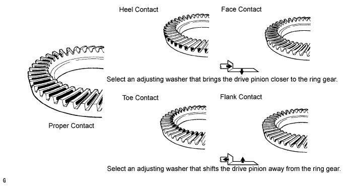
INSPECT TOOTH CONTACT BETWEEN RING GEAR AND DRIVE PINION
-
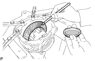
Coat 3 or 4 teeth at the 3 different positions on the ring gear with Prussian blue.
-
Rotate the ring gear in both directions.
-
Inspect the tooth contact pattern.
-
If the teeth are not contacting properly, use the following table to select a proper plate washer for correction.
Tech Tips
-
If the contact pattern is face contact or flank contact, tooth contact may be adjustable while keeping the backlash within the specified range.
-
If the thickness of the drive pinion washer has been changed, adjust the backlash and measure the total preload.
Washer thickness Thickness mm (in.) No. Thickness mm (in.) No. Thickness mm (in.) No. 1.88 (0.0740) 88 2.02 (0.0795) 02 2.16 (0.0850) 16 1.90 (0.0748) 90 2.04 (0.0803) 04 2.18 (0.0858) 18 1.92 (0.0756) 92 2.06 (0.0811) 06 2.20 (0.0866) 20 1.94 (0.0764) 94 2.08 (0.0819) 08 2.22 (0.0874) 22 1.96 (0.0772) 96 2.10 (0.0827) 10 2.24 (0.0882) 24 1.98 (0.0780) 98 2.12 (0.0835) 12 2.26 (0.0890) 26 2.00 (0.0787) 00 2.14 (0.0843) 14 2.28 (0.0898) 28 -
-
-
REMOVE REAR DIFFERENTIAL SIDE GEAR SHAFT SNAP RING (for RH Side)
-
Install SST to the rear differential carrier with the 2 bolts.
- SST
- 09571-50010
-
Install a dial indicator to the rear differential carrier.
-
Tighten the SST bolt and alter the shape of the differential carrier to create a 0.1 mm (0.00394 in.) clearance between the differential side bearing outer race RH and side gear shaft snap ring.
Note
Observe the dial indicator to ensure that the shape of the differential carrier does not change more than 0.2 mm (0.00787 in.).
Tech Tips
-
Set the dial indicator to the rearmost position (upper side in the illustration) of the area around where the side oil seal is tapped in.
-
Approximately 0.1 mm (0.00394 in.) clearance between the differential side bearing outer race RH and the side gear shaft snap ring is sufficient for the washer to move slightly.
-
-
Using snap ring pliers, remove the side gear shaft snap ring on the ring gear tooth side.
-
Remove the dial indicator and loosen the SST bolt.
Note
Do not remove SST.
-
-
REMOVE REAR DIFFERENTIAL SIDE GEAR SHAFT SNAP RING (for LH Side)
-
Using SST and a hammer, create a clearance between the differential side bearing outer race LH on the ring gear and side gear shaft snap ring.
- SST
- 09608-32010
- 09950-70010 ( 09951-07200 )
Tech Tips
The clearance is not visible, but tapping SST with a hammer 3 or 4 times should be enough.
-
Using snap ring pliers, remove the side gear shaft snap ring on the ring gear back surface side.
-
-
REMOVE DIFFERENTIAL SIDE BEARING OUTER RACE LH
-
Tighten the SST bolt and push out the differential side bearing outer race LH on the ring gear back surface side.
- SST
- 09571-50010
Note
Do not drop the side bearing outer race.
Tech Tips
-
To use as a reference for installation, clearly write the installation positions (back side or teeth side) of the differential side bearing outer race and the rear differential side gear shaft snap ring.
-
Put identification marks on the differential side bearing outer race to show the location for installation (back side or teeth side), or keep them separate so that they can be distinguished.
-
Remove the 2 bolts and SST.
-
-
REMOVE DIFFERENTIAL SIDE BEARING OUTER RACE RH
-
Raise the ring gear side of the differential case slightly to remove the ring gear tooth side differential side bearing outer race RH.
Tech Tips
-
For reassembly, check the installation position of the differential side bearing outer race and the side gear shaft snap ring before removing the differential side bearing outer race. Write down the result.
-
Put identification marks on the differential side bearing outer race to show the location for installation (back side or teeth side), or keep them separate so that they can be distinguished.
-
-
-
REMOVE REAR DIFFERENTIAL CASE SUB-ASSEMBLY
-
Remove the rear differential case assembly.
Note
Do not damage the case bearing.
-
-
REMOVE REAR DRIVE PINION NUT
-
Using SST to hold the flange, remove the drive pinion nut.
- SST
- 09229-55010
- 09330-00021
- 09950-30012 ( 09955-03040 )
-
-
REMOVE REAR DRIVE PINION COMPANION FLANGE
-
Using SST, remove the companion flange.
- SST
- 09950-30012 ( 09951-03010, 09953-03010, 09954-03010, 09955-03040, 09956-03060 )
Note
Apply grease to the threads and tip of the SST center bolt before use.
-
-
REMOVE REAR DIFFERENTIAL DRIVE PINION OIL SLINGER
-
Remove the differential drive pinion oil slinger.
-
-
REMOVE DIFFERENTIAL DRIVE PINION
-
Using a press, remove the drive pinion from the differential carrier.
Note
Do not drop the drive pinion.
-
-
REMOVE REAR DRIVE PINION FRONT TAPERED ROLLER BEARING
-
Remove the rear drive pinion front tapered roller bearing from the differential carrier.
-
-
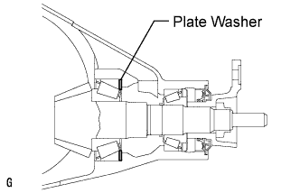
INSTALL REAR DIFFERENTIAL DRIVE PINION BEARING SPACER
-
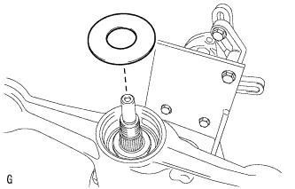
Install a new rear differential drive pinion bearing spacer to the differential drive pinion as shown in the illustration.
-
-
INSTALL REAR DRIVE PINION FRONT TAPERED ROLLER BEARING
-
Install the rear drive pinion front tapered roller bearing to the differential carrier.
-
-
INSTALL DIFFERENTIAL DRIVE PINION
-
Using SST and a press, install the differential drive pinion to the differential carrier.
- SST
- 09316-60011 ( 09316-00011, 09316-00041 )
- 09608-04031
-
-
INSTALL REAR DIFFERENTIAL DRIVE PINION OIL SLINGER
-
Install the differential drive pinion oil slinger to the differential drive pinion.
-
-
INSTALL REAR DIFFERENTIAL CARRIER OIL SEAL
-
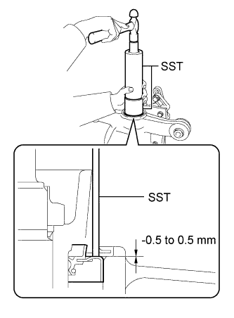
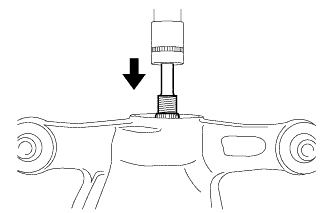
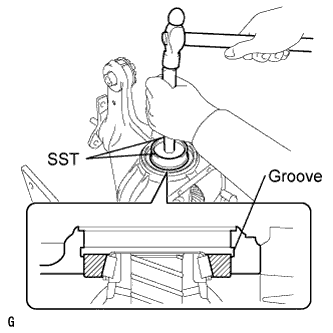
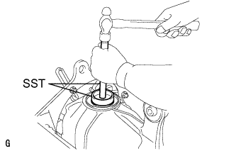
Using SST and a hammer, install a new rear differential carrier oil seal.
- SST
- 09316-60011 ( 09316-00011 )
- 09710-30012 ( 09710-04101 )
Note
-
Tap the oil seal uniformly so that the oil seal is straight.
-
Do not excessively tap the oil seal.
-
Using a vernier caliper, measure the depth of the oil seal.
Standard depth -0.5 to 0.5 mm (-0.0197 to 0.0197 in.) Note
-
Measure at 3 or more areas around the circumference of the oil seal.
-
Make sure difference between the maximum and minimum measured values is less than 0.65 mm (0.0256 in.), as a greater difference may lead to oil leaks.
-
-
Apply MP grease to the oil seal lip.
-
-
INSTALL REAR DRIVE PINION COMPANION FLANGE
-
Using SST, install the companion flange to the drive pinion.
- SST
- 09950-30012 ( 09951-03010, 09953-03010, 09954-03010, 09955-03040, 09956-03060 )
Note
Apply grease to the threads and tip of the SST center bolt before use.
-
Coat the threads of a new drive pinion nut with hypoid gear oil LSD.
-
Using SST and a torque wrench, hold the flange and tighten the drive pinion nut.
- SST
- 09229-55010
- 09330-00021
- 09950-30012 ( 09955-03040 )
Torque 490 N*m (5000 kgf*cm, 361 ft.*lbf) or less Note
-
Do not tighten excessively, otherwise the threads will be stripped.
-
Apply hypoid gear oil LSD to the threads of the nut and drive pinion.
Tech Tips
Tighten the nut to approximately 100 N*m (1020 kgf*cm, 74 ft.*lbf), then tighten it further while observing the preload.
-
-
INSTALL REAR DIFFERENTIAL CASE SUB-ASSEMBLY
-
Insert the differential case from the ring gear tooth side.
Note
Do not damage the case bearing inner race or ring gear.
-
-
INSTALL DIFFERENTIAL SIDE BEARING OUTER RACE RH
-
Using SST and a hammer, install the ring gear tooth side differential side bearing outer race RH.
- SST
- 09608-32010
- 09950-70010 ( 09951-07200 )
Tech Tips
Tap in the differential side bearing outer race until half of the side gear shaft snap ring groove of the differential carrier can be seen.
-
-
INSTALL DIFFERENTIAL SIDE BEARING OUTER RACE LH
-
Install SST to the differential carrier with the 2 bolts.
- SST
- 09571-50010
-
Tighten the SST bolt (A) until the SST disc lightly touches the differential side bearing outer race RH.
-
Using SST and a hammer, install the ring gear back surface side differential side bearing outer race LH.
- SST
- 09608-32010
- 09950-70010 ( 09951-07200 )
Tech Tips
Tap in the differential side bearing outer race until it touches the case bearing inner race roller.
-
-
INSTALL REAR DIFFERENTIAL SIDE GEAR SHAFT SNAP RING
-
Using snap ring pliers, install the side gear shaft snap ring in the differential carrier on the ring gear back surface side.
Tech Tips
Use the side gear shaft snap ring installed when performing tooth contact adjustment.
-
Set a dial indicator on the differential carrier.
-
Tighten the SST bolt and alter the shape of the differential carrier to create a 0.1 mm (0.00394 in.) clearance between the differential side bearing outer race RH and side gear shaft snap ring.
Note
Observe the dial indicator to ensure that the clearance does not change more that 0.2 mm (0.00787 in.).
-
Using snap ring pliers, install the side gear shaft snap ring on the ring gear tooth side.
Tech Tips
Use the side gear shaft snap ring installed when performing tooth contact adjustment.
-
Remove the dial indicator and tap the differential carrier on the ring gear tooth side using a plastic hammer to stabilize the case bearing.
-
Remove the 2 bolts and SST.
-
-
ADJUST DIFFERENTIAL DRIVE PINION PRELOAD
-
Using SST and a torque wrench, measure the preload.
- SST
- 09229-55010
Differential drive pinion preload (starting torque) 1.25 to 1.65 N*m (13 to 16 kgf*cm, 12 to 14 in.*lbf)
-
If the preload is less than the specified minimum value, check the preload while retightening the drive pinion nut 5 to 10°.
Torque 490 N*m (5000 kgf*cm, 361 ft.*lbf) or less -
If the preload is less than the specified minimum value even when the tightening torque of the drive pinion nut is greater than the specified maximum value, loosen the nut and check that the threads of the drive pinion nut and drive pinion are not stripped.
-
If the threads are not stripped, replace the bearing spacer. Apply hypoid gear oil LSD to the threads of the drive pinion and repeat the procedure.
-
-
INSPECT TOTAL PRELOAD
-
Using SST and a torque wrench, measure the preload with the teeth of the drive pinion and ring gear in contact.
- SST
- 09229-55010
Total preload (starting torque) New bearing 1.91 to 3.51 N*m (20 to 35 kgf*cm, 17 to 31 in.*lbf) Reused bearing 1.74 to 2.96 N*m (18 to 30 kgf*cm, 16 to 26 in.*lbf)
-
-
INSPECT DIFFERENTIAL RING GEAR BACKLASH
-
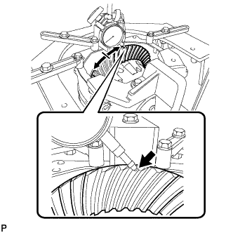
While holding the rear drive pinion companion flange, rotate the ring gear and measure the backlash.
Backlash 0.08 to 0.13 mm (0.00315 to 0.00512 in.) If the backlash is not within the specified range, adjust the backlash or repair as necessary.
-
-
INSPECT RUNOUT OF DIFFERENTIAL DRIVE PINION
-
Using a dial indicator, measure the runout of the drive pinion shaft at a position 10 mm (0.394 in.) away from the end of the shaft.
Maximum runout 0.08 mm (0.00315 in.) If the runout is greater than the maximum, replace the drive pinion and ring gear.
-
-
STAKE REAR DRIVE PINION NUT
-
Using SST and a hammer, stake the drive pinion nut.
- SST
- 09930-00010
-
-
INSTALL REAR DIFFERENTIAL SIDE GEAR SHAFT OIL SEAL
-
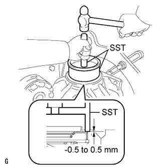
Using SST and a hammer, install 2 new oil seals.
- SST
- 09223-15030
- 09950-70010 ( 09951-07200 )
Oil seal installation depth -0.5 to 0.5 mm (-0.0197 to 0.0197 in.) Tech Tips
-
Make sure to check the identification marks on the oil seals before installation because the parts numbers differ between the left and right sides.
-
To ensure a proper seal, evenly tap in the rear differential side gear shaft oil seals.
-
After installing both oil seals, tap them in until both surfaces are flush with the rear differential carrier.
-
Apply MP grease to the oil seal lips.
-
-
INSTALL REAR DIFFERENTIAL DRAIN PLUG
-
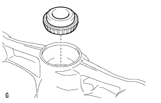
Using a hexagon wrench (10 mm), install the differential drain plug with a new gasket.
- Torque:
- 49 N*m { 500 kgf*cm, 36 ft.*lbf }
-
-
TEMPORARILY TIGHTEN REAR DIFFERENTIAL FILLER PLUG
-
Using a hexagon wrench (10 mm), temporarily install the differential filler plug.
Tech Tips
Add differential oil before installing the gasket and fully tightening the rear differential filler plug.
-
-
REMOVE REAR DIFFERENTIAL CARRIER
-
Remove the 4 bolts and differential carrier from the overhaul attachment.
Note
Clean the fitting surface between the differential carrier and carrier cover.
-
-
INSTALL REAR DIFFERENTIAL CARRIER COVER
-
Clean the seal packing attached on the differential carrier and carrier cover using a scraper and wire brush. Then remove the oil with non-residue solvent or equivalent.
Note
Do not scratch the sealing surface.
-
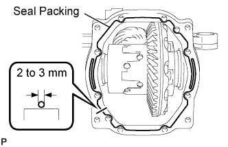
Apply seal packing to the differential carrier as shown in the illustration.
Seal packing Toyota Genuine Seal Packing 1281, Three bond 1281 or equivalent Note
-
Apply the seal packing in a continuous line, approximately 2 to 3 mm (0.0787 to 0.118 in.) in diameter.
-
Overlap the seal packing at least 10 mm (0.394 in.) at the beginning and the end of application.
-
Install the differential carrier cover within 3 minutes of application.
-
-
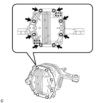
Install the differential carrier cover with the 8 bolts and 2 pins.
- Torque:
- 47 N*m { 479 kgf*cm, 35 ft.*lbf }
Note
Do not fill the oil or drive immediately after installing the differential carrier cover. Leave the vehicle for at least 1 hour. Also, avoid sudden acceleration and deceleration for at least 72 hours after application.
-
-
INSTALL REAR DIFFERENTIAL CARRIER ASSEMBLY
-
Install the rear differential carrier assembly Click here.
-