REAR DIFFERENTIAL CARRIER ASSEMBLY INSPECTION

-
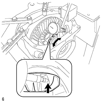
INSPECT RUNOUT OF DIFFERENTIAL RING GEAR
-
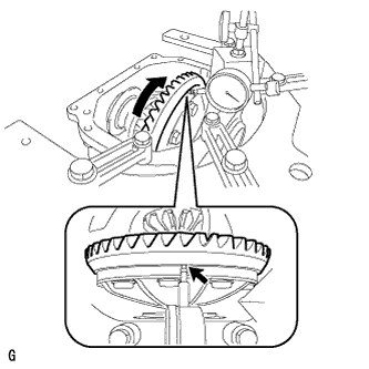
Set the dial indicator perpendicular to the end of the ring gear face.
-
Rotate the ring gear and measure the backlash.
Maximum runout 0.04 mm (0.00157 in.) If the runout exceeds the specified maximum value, remove the ring gear and check the runout of the differential case.
-
-
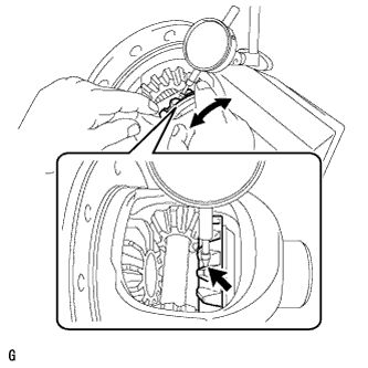
INSPECT DIFFERENTIAL RING GEAR BACKLASH
-
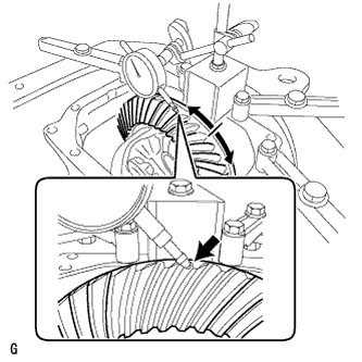
While holding the rear drive pinion companion flange, rotate the ring gear and measure the backlash.
Backlash 0.08 to 0.13 mm (0.00315 to 0.00512 in.) If the backlash is not within the specified range, adjust the backlash or repair as necessary.
-
-
INSPECT TOOTH CONTACT BETWEEN RING GEAR AND DRIVE PINION
-
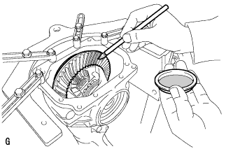
Coat 3 or 4 teeth at the 3 different positions on the ring gear with prussian blue.
-
Rotate the ring gear in both directions.
-
Inspect the tooth contact pattern.
-
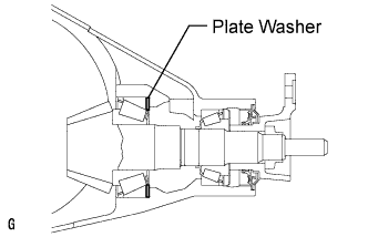
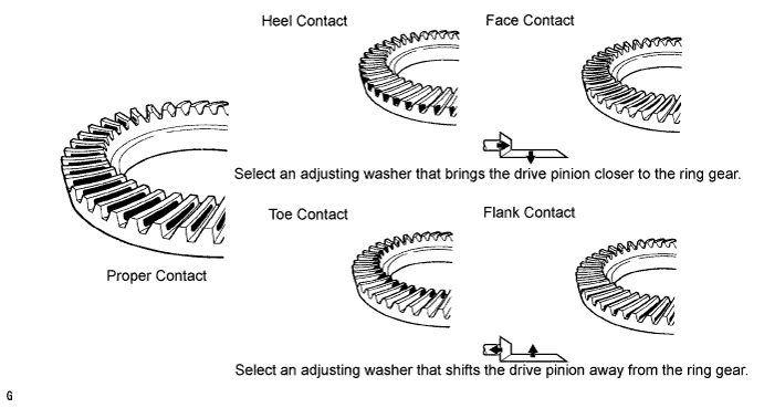
If the teeth are not contacting properly, use the following table to select a proper plate washer for correction.
Tech Tips
-
If the contact pattern is face contact or flank contact, tooth contact may be adjustable while keeping the backlash within the specified range.
-
If the thickness of the drive pinion washer has been changed, adjust the backlash and measure the total preload.
Washer Thickness Thickness mm (in.) No. Thickness mm (in.) No. Thickness mm (in.) No. 1.87 (0.0736) 87 2.01 (0.0791) 01 2.15 (0.0846) 15 1.88 (0.0740) 88 2.02 (0.0795) 02 2.16 (0.0850) 16 1.89 (0.0744) 89 2.03 (0.0799) 03 2.17 (0.0854) 17 1.90 (0.0748) 90 2.04 (0.0803) 04 2.18 (0.0858) 18 1.91 (0.0752) 91 2.05 (0.0807) 05 2.19 (0.0862) 19 1.92 (0.0756) 92 2.06 (0.0811) 06 2.20 (0.0866) 20 1.93 (0.0760) 93 2.07 (0.0815) 07 2.21 (0.0870) 21 1.94 (0.0764) 94 2.08 (0.0819) 08 2.22 (0.0874) 22 1.95 (0.0768) 95 2.09 (0.0823) 09 2.23 (0.0878) 23 1.96 (0.0772) 96 2.10 (0.0827) 10 2.24 (0.0882) 24 1.97 (0.0776) 97 2.11 (0.0831) 11 2.25 (0.0886) 25 1.98 (0.0780) 98 2.12 (0.0835) 12 2.26 (0.0890) 26 1.99 (0.0783) 99 2.13 (0.0839) 13 2.27 (0.0894) 27 2.00 (0.0787) 00 2.14 (0.0843) 14 2.28 (0.0898) 28 -
-
-
INSPECT DIFFERENTIAL SIDE GEAR BACKLASH
-
Place a dial indicator on the tip of the pinion gear tooth at a right angle. Hold the side gear in the differential case and check that the backlash is 0.15 mm (0.00591 in.) or less.
If not, replace the rear differential case sub-assembly with a new one.
-
-
INSPECT DIFFERENTIAL SIDE GEAR BACKLASH
-
Secure the differential case in a vise between aluminum plates.
Note
Do not overtighten the vise.
-
Place a dial indicator on the tip of the side gear tooth at a right angle. Hold the pinion gear in the differential case and check that the backlash is 0.15 mm (0.00591 in.) or less.
If not, replace the rear differential case sub-assembly with a new one.
-
-
INSPECT RUNOUT OF DIFFERENTIAL DRIVE PINION
-
Using a dial indicator, measure the runout of the drive pinion shaft at a position 10 mm (0.394 in.) away from the end of the shaft.
Maximum runout 0.08 mm (0.00315 in.) If the runout is greater than the maximum, replace the drive pinion and ring gear.
-
-
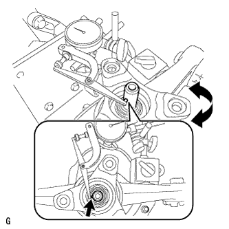
INSPECT DIFFERENTIAL DRIVE PINION PRELOAD
-
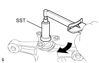
Using SST and a torque wrench, measure the starting torque of the drive pinion. The backlash between the drive pinion and ring gear should allow enough movement of the drive pinion to allow this measurement to be performed. Make sure not to include the preload of the ring gear (differential case) in the measurement of the drive pinion preload.
Differential Drive Pinion Preload (at Starting) A Type Item Specified Condition New rear drive pinion tapered roller bearing 1.25 to 1.65 N*m (12.75 to 16.83 kgf*cm, 11.06 to 14.60 in.*lbf) Used rear drive pinion tapered roller bearing 1.25 to 1.65 N*m (12.75 to 16.83 kgf*cm, 11.06 to 14.60 in.*lbf) B Type Item Specified Condition New rear drive pinion tapered roller bearing 1.44 to 2.01 N*m (14.68 to 20.50 kgf*cm, 12.74 to 17.79 in.*lbf) Used rear drive pinion tapered roller bearing 0.50 to 0.80 N*m (5.10 to 8.16 kgf*cm, 4.43 to 7.08 in.*lbf) If the preload is not within the specified range, adjust the rear differential drive pinion preload or repair as necessary.
-
-
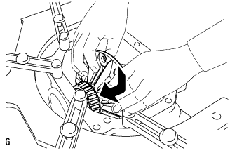
INSPECT TOTAL PRELOAD
-
Using SST and a torque wrench, measure the preload with the teeth of the drive pinion and ring gear in contact.
Total Preload (at Starting) A Type Item Specified Condition New rear drive pinion tapered roller bearing 1.91 to 3.51 N*m (19.48 to 35.79 kgf*cm, 16.90 to 31.07 in.*lbf) Used rear drive pinion tapered roller bearing 1.74 to 2.96 N*m (17.74 to 30.18 kgf*cm, 15.40 to 26.20 in.*lbf) B Type Item Specified Condition New rear drive pinion tapered roller bearing 2.10 to 3.87 N*m (21.41 to 39.46 kgf*cm, 18.59 to 34.25 in.*lbf) Used rear drive pinion tapered roller bearing 0.99 to 2.11 N*m (10.10 to 21.52 kgf*cm, 8.76 to 18.67 in.*lbf)
-
-
INSPECT RUNOUT OF REAR DIFFERENTIAL CASE SUB-ASSEMBLY
Tech Tips
Perform this procedure only when the runout of the differential ring gear exceeds the specified maximum value.
-
Install the differential case to the differential carrier.
Note
Do not damage the case bearing.
-
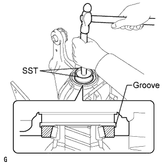
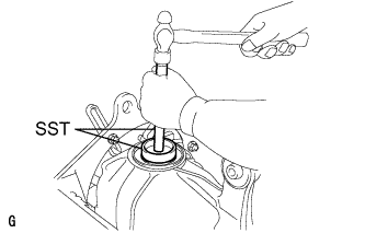
Using SST and a hammer, install the differential side bearing outer race RH on the ring gear tooth side.
- SST
- 09608-32010
- 09950-70010 ( 09951-07200 )
Tech Tips
Tap in the differential side bearing outer race RH until half of the side gear shaft snap ring groove of the differential carrier can be seen.
-
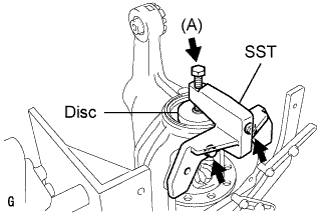
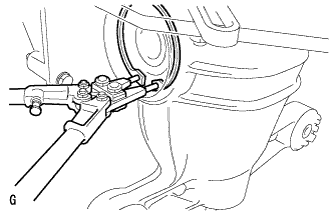
Install SST to the differential carrier with the 2 bolts.
- SST
- 09571-50010
-
Tighten the SST bolt (A) until the SST disc lightly touches the differential side bearing outer race RH.
-
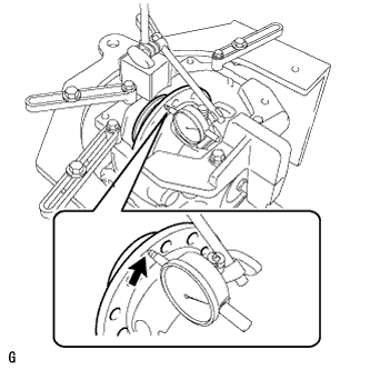
Using SST and a hammer, install the differential side bearing outer race LH on the ring gear back surface side.
- SST
- 09608-32010
- 09950-70010 ( 09951-07200 )
Tech Tips
Tap in the differential side bearing outer race LH until it touches the case bearing inner race roller.
-
Using snap ring pliers, install the side gear shaft snap ring in the differential carrier on the ring gear back surface side.
-
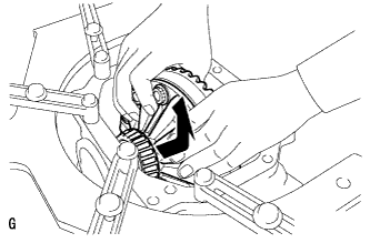
Place a dial indicator on the differential case flange surface at a right angle.
-
Using a dial indicator, measure the differential case runout.
Maximum runout 0.04 mm (0.00157 in.) If the runout is greater than the maximum, replace the rear differential case with a new one.
-
Using snap ring pliers, remove the side gear shaft snap ring on the ring gear back surface side.
-
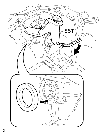
Tighten the SST bolt to push out the ring gear back surface side differential side bearing outer race LH.
Note
Do not drop the differential side bearing outer race LH.
-
Remove the 2 bolts and SST.
-
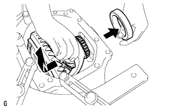
Raise the ring gear side of the differential case slightly to remove the ring gear tooth side differential side bearing outer race RH.
-
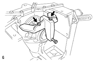
Remove the differential case from the differential carrier as shown in the illustration.
Note
Do not damage the case bearing.
-