FRONT AXLE HUB ON-VEHICLE INSPECTION

Tech Tips
-
Use the same procedure for the RH side and LH side.
-
The procedure listed below is for the LH side.
-
REMOVE FRONT WHEEL
-
SEPARATE FRONT DISC BRAKE CYLINDER ASSEMBLY
-
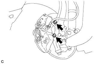
Remove the 2 bolts and separate the front disc brake cylinder assembly.
Note
Use a wire or an equivalent tool to hang the front disc brake cylinder assembly.
-
-
REMOVE FRONT DISC
-
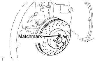
Remove the front disc from the front axle hub.
Tech Tips
Put matchmarks on the disc and axle hub.
-
-
INSPECT FRONT AXLE HUB BEARING LOOSENESS
-
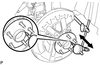
Using a dial indicator, check for looseness near the center of the front axle hub.
Maximum looseness 0.05 mm (0.00196 in.) Note
Ensure that the dial indicator is perpendicular to the measurement surface.
If the looseness exceeds the maximum, replace the front axle hub and bearing assembly.
-
-
INSPECT FRONT AXLE HUB RUNOUT
-
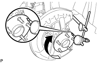
Using a dial indicator, check for runout on the surface of the axle hub outside the hub bolt.
Maximum runout 0.05 mm (0.00196 in.) Note
Ensure that the dial indicator is set perpendicular to the measurement surface.
If the runout exceeds the maximum, replace the front axle hub and bearing assembly.
-
-
INSTALL FRONT DISC
-
Align the matchmarks of the disc and axle hub, and install the front disc.
Note
When replacing the disc with a new one, select the installation position where the front disc has minimal runout.
-
-
INSTALL FRONT DISC BRAKE CYLINDER ASSEMBLY
-
Install the front disc brake cylinder assembly with the 2 bolts.
- Torque:
- 78 N*m { 795 kgf*cm, 58 ft.*lbf }
Note
Do not twist the brake hose when installing the front disc brake cylinder assembly.
-
-
INSTALL FRONT WHEEL
- Torque:
- 103 N*m { 1050 kgf*cm, 76 ft.*lbf }