PROPELLER SHAFT ASSEMBLY REASSEMBLY

-
INSTALL NO. 1 CENTER SUPPORT BEARING ASSEMBLY
Note
Be careful not to grip the propeller shaft tube too tightly in a vise as this may cause deformation.
-
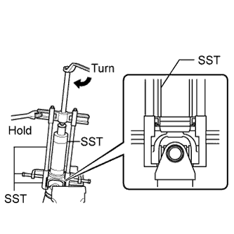
Using SST, install a new No. 1 propeller shaft dust deflector.
- SST
- 09506-35010
- 09316-60011 ( 09316-00011 )
- 09950-40011 ( 09951-04020, 09952-04010, 09953-04030, 09955-04021, 09958-04011 )
Note
Be careful not to damage the No. 1 propeller shaft dust deflector.
-
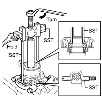
Using SST, install the No. 1 center support bearing assembly.
- SST
- 09950-40011 ( 09951-04020, 09953-04030 )
- 09330-50010
- 09950-00020
- 09950-50013 ( 09952-05010 )
Note
Be sure to install the bearing in the correct direction.
-
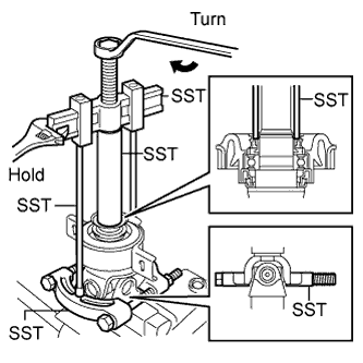
Using SST, insert a new No. 2 propeller shaft dust deflector until it almost touches the rubber of the No. 1 center support bearing assembly.
- SST
- 09950-40011 ( 09951-04020, 09953-04030 )
- 09330-50010
- 09950-00020
- 09950-50013 ( 09952-05010 )
Note
Be careful not to damage the No. 2 propeller shaft dust deflector.
-
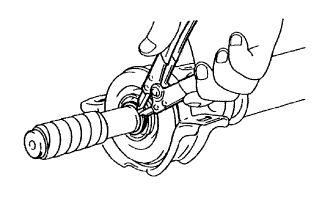
Using a snap ring expander, install a new No. 2 propeller shaft dust deflector snap ring.
-
-
INSTALL PROPELLER INTERMEDIATE SHAFT
-
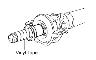
Install the dust boot.
Note
Assemble the propeller intermediate shaft assembly after wrapping vinyl tape around the spline to prevent damage.
-
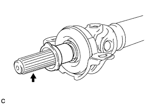
Apply grease to the splines.
Grease Molybdenum disulphide lithium base NLGI No. 2 -
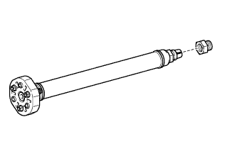
Install the adjusting nut to the intermediate shaft.
-
Align the matchmarks and assemble the intermediate shaft and propeller shaft.
-
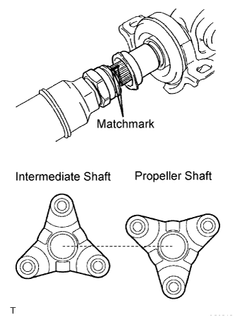
Cover the adjusting nut with the dust boot.
Note
The alignment of the intermediate shaft companion flange and the propeller shaft companion flange should differ by 180°.
-
Temporarily tighten the adjusting nut by hand.
-