AUTOMATIC TRANSMISSION UNIT REASSEMBLY

-
BEARING POSITION
Bearing Position Position Front Race Diameter
Inside/Outside
Thrust Bearing Diameter
Inside/Outside
Rear Race Diameter
Inside/Outside
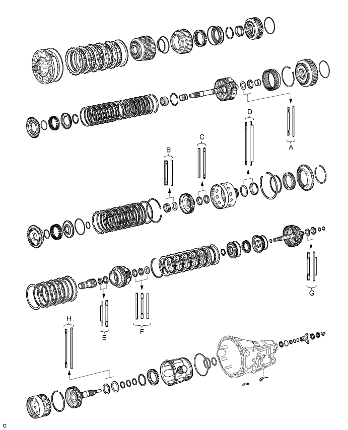
A - 36.2 mm (1.43 in.) / 58.2 mm (2.30 in.) 44.0 mm (1.73 in.) / 62.0 mm (2.44 in.) B - 34.5 mm (1.36 in.) / 49.4 mm (1.94 in.) 36.6 mm (1.44 in.) / 51.9 mm (2.04 in.) C 46.5 mm (1.83 in.) / 60.1 mm (2.37 in.) 47.0 mm (1.85 in.) / 61.9 mm (2.44 in.) - D - 71.9 mm (2.83 in.) / 85.6 mm (3.37 in.) 72.7 mm (2.86 in.) / 89.2 mm (3.51 in.) E 30.0 mm (1.18 in.) / 49.9 mm (1.96 in.) 31.0 mm (1.22 in.) / 53.1 mm (2.09 in.) - F 31.5 mm (1.24 in.) / 53.0 mm (2.09 in.) 28.7 mm (1.13 in.) / 52.3 mm (2.06 in.) 28.7 mm (1.13 in.) / 50.4 mm (1.98 in.) G - 30.5 mm (1.20 in.) / 55.7 mm (2.19 in.) 33.5 mm (1.32 in.) / 59.0 mm (2.32 in.) H - 58.9 mm (2.32 in.) / 77.3 mm (3.04 in.) 62.0 mm (2.44 in.) / 82.5 mm (3.25 in.) -
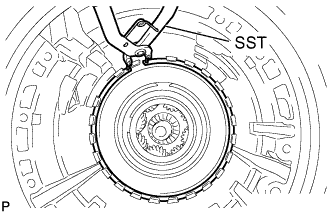
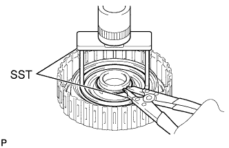
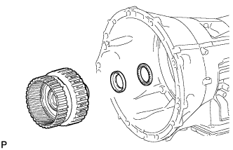
INSTALL REAR OUTPUT SHAFT RADIAL BALL BEARING
-
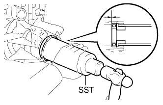
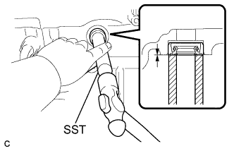
Using SST, fully tap the bearing into the transmission case.
- SST
- 09316-60011 ( 09316-00011, 09316-00021 )
-
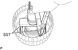
Using needle-nose pliers, install the snap ring.
-
-
INSTALL REAR AUTOMATIC TRANSMISSION OIL SEAL
-
Coat the lip of a new oil seal with MP grease.
-
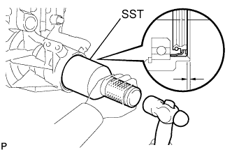
Using SST and a hammer, tap the oil seal into the transmission case.
- SST
- 09214-76011
Standard oil seal depth 3.3 to 3.7 mm (0.130 to 0.146 in.)
-
-
INSTALL BRAKE PLATE STOPPER SPRING
-
Install the 2 brake plate stopper springs.
-
-
INSTALL NO. 2 BRAKE PISTON
-
Coat 3 new O-rings with ATF, and install them to the No. 2 brake piston.
-
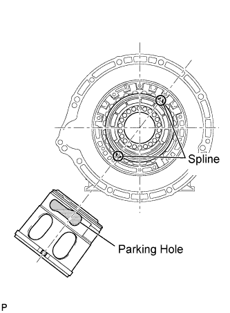
Install the No. 2 brake piston to the transmission case.
Tech Tips
Make sure that the parking hole of the No. 2 brake piston is on the bottom side by engaging the 2 brake piston protrusions to the transmission case spline grooves. (One groove is 3 places clockwise from the top, and the other is 2 places clockwise from the bottom as shown in the illustration).
-
Install the No. 2 brake piston return spring to the transmission case.
-
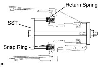
Set SST on the No. 2 brake piston return spring, tighten SST and compress the return spring.
- SST
- 09380-50010
-
Using SST, install the snap ring.
- SST
- 09350-30020 ( 09350-07070 )
-
-
SELECT NO. 2 BRAKE FLANGE
-
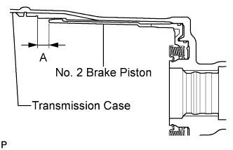
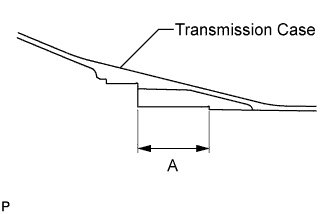
Measure length A (from the tip of the No. 2 brake piston to the step in the transmission case) in the illustration.*1
Standard length 14.77 to 15.37 mm (0.581 to 0.605 in.) -
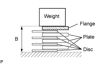
Assemble the 4 No. 2 brake discs, 3 No. 2 brake plates, and No. 2 brake flange as shown in the illustration. Then, with a weight of 500 g (17.64 oz ) or less placed on the flange, measure length B.*2
Standard 14.11 to 14.69 mm (0.556 to 0.578 in.) -
Choose a No. 2 brake flange from the table so that the value of measured length A minus length B (from steps *1 and *2) will be 0.52 to 0.82 mm (0.0205 to 0.0323 in.).
Flange Thickness Mark Thickness 0 1.95 to 2.05 mm (0.0768 to 0.0807 in.) 1 2.05 to 2.15 mm (0.0807 to 0.0846 in.) 2 2.15 to 2.25 mm (0.0846 to 0.0886 in.) 3 2.25 to 2.35 mm (0.0886 to 0.0925 in.) 4 2.35 to 2.45 mm (0.0925 to 0.0965 in.) 5 2.45 to 2.55 mm (0.0965 to 0.100 in.) 6 2.55 to 2.65 mm (0.100 to 0.104 in.) 7 2.65 to 2.75 mm (0.104 to 0.108 in.) 8 2.75 to 2.85 mm (0.108 to 0.112 in.)
-
-
INSTALL DIRECT CLUTCH PISTON
-
Coat a new O-ring with ATF, and install it to the direct clutch drum sub-assembly.
-
Coat a new O-ring with ATF, and install it to the direct clutch piston.
-
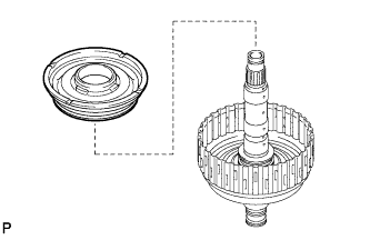
Install the direct clutch piston to the direct clutch drum sub-assembly.
-
Coat a new O-ring with ATF, and install it to the No. 2 clutch balancer.
-
Install the direct clutch piston return spring sub-assembly and No. 2 clutch balancer to the direct clutch drum sub-assembly.
-
Place SST on the No. 2 clutch balancer and compress the return spring with a press.
- SST
- 09387-00020
-
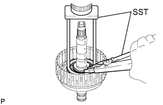
Using SST, install the snap ring.
- SST
- 09350-30020 ( 09350-07070 )
-
-
INSTALL NO. 2 CLUTCH DISC SET
-
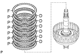
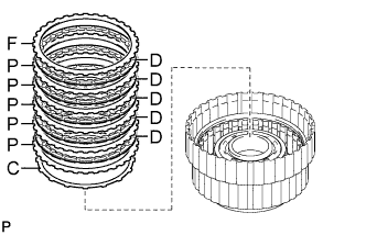
Install the 6 plates, 6 discs and flange to the direct clutch drum.
Install in order P - D - P - D - P - D - P - D - P - D - P - D - F Tech Tips
P = Plate
D = Disc
F = Flange
Note
Before assembling new discs, soak them in ATF for at least 2 hours.
-
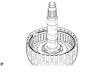
Temporarily install the snap ring.
-
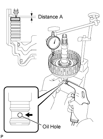
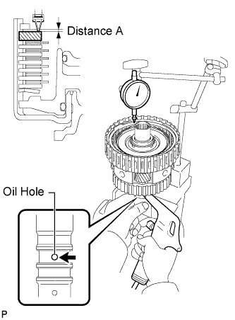
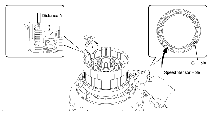
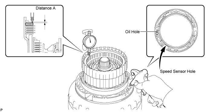
Using a dial indicator, measure the distance (distance A) the clutch flange moves at both ends while blowing compressed air (196 kPa, 2.0 kgf*cm2, 28 psi) from the oil hole as shown in the illustration. Then choose from the 9 flange thicknesses in the table so that the measured value will be within the standard range.
Standard 0.90 to 1.20 mm (0.0354 to 0.0472 in.) Flange Thickness Mark Thickness 40 3.95 to 4.05 mm (0.156 to 0.159 in.) 41 4.05 to 4.15 mm (0.159 to 0.163 in.) 42 4.15 to 4.25 mm (0.163 to 0.167 in.) 43 4.25 to 4.35 mm (0.167 to 0.171 in.) 44 4.35 to 4.45 mm (0.171 to 0.175 in.) 45 4.45 to 4.55 mm (0.175 to 0.179 in.) 46 4.55 to 4.65 mm (0.179 to 0.183 in.) 47 4.65 to 4.75 mm (0.183 to 0.187 in.) 48 4.75 to 4.85 mm (0.187 to 0.191 in.) -
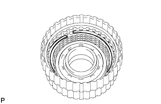
Temporarily remove the snap ring, install the selected flange and reinstall the snap ring.
-
-
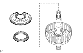
CONNECT DIRECT CLUTCH ASSEMBLY
-
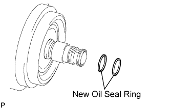
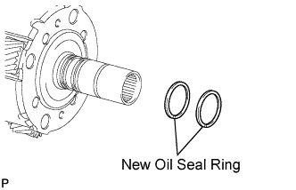
Coat 2 new oil seal rings with ATF, and install them to the direct clutch drum sub-assembly.
Note
Do not expand the ring ends excessively.
-
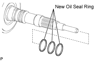
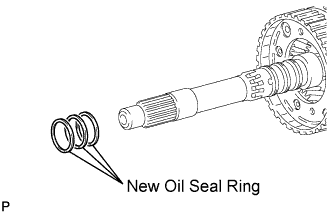
Coat 3 new oil seal rings with ATF, and install them to the output shaft.
Note
Do not expand the ring ends excessively.
-
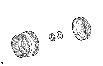
Install the thrust needle roller bearing and thrust bearing race.
Standard Bearing and Race Diameter Item Inside Outside Bearing 30.5 mm (1.20 in.) 55.7 mm (2.19 in.) Race 33.5 mm (1.32 in.) 59.0 mm (2.32 in.) Note
Use a small amount of MP grease to secure the thrust bearing and thrust bearing race in place.
-
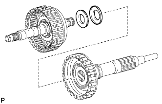
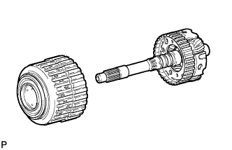
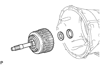
Install the direct clutch assembly to the output shaft.
-
-
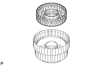
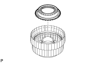
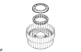
INSTALL REAR PLANETARY RING GEAR
-
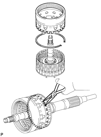
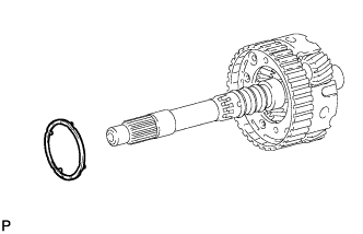
Install the snap ring to the groove of the output shaft.
-
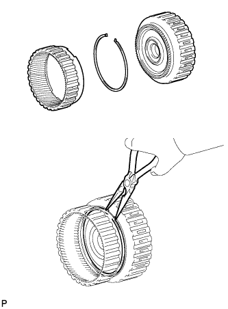
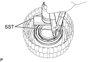
Using needle-nose pliers, attach the snap ring to install the ring gear to the output shaft.
-
-
INSTALL DIRECT CLUTCH ASSEMBLY WITH REAR PLANETARY RING GEAR AND OUTPUT SHAFT SUB-ASSEMBLY
-
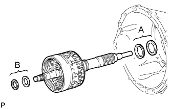
Install the 2 thrust needle bearings, 2 thrust bearing races, direct clutch with rear planetary ring gear and output shaft to the transmission case.
Standard Bearing and Race Diameter Item Inside Outside Race A 62.0 mm (2.44 in.) 82.5 mm (3.25 in.) Bearing A 58.9 mm (2.32 in.) 77.3 mm (3.04 in.) Race B 28.7 mm (1.13 in.) 50.4 mm (1.98 in.) Bearing B 28.7 mm (1.13 in.) 52.3 mm (2.06 in.) Note
Use a small amount of MP grease to secure the thrust bearing and thrust bearing race in place.
-
-
INSTALL AUTOMATIC TRANSMISSION FLANGE YOKE ASSEMBLY
-
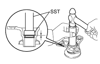
Using SST, install a new oil seal to the automatic transmission flange yoke.
- SST
- 09950-60010 ( 09951-00410 )
- 09950-70010 ( 09951-07100 )
Standard depth 0 to 0.3 mm (0 to 0.0118 in.) -
Install the rear cover sleeve and 2 output shaft rear bearing No. 1 spacers.
-
Install the automatic transmission flange yoke.
-
Set SST.
- SST
- 09330-00021
- 09950-30012 ( 09955-03040 )
-
Using SST and a 30 mm socket wrench, temporarily install and tighten a new nut.
- Torque:
- 135 N*m { 1376 kgf*cm, 99 ft.*lbf }
-
-
SELECT REAR COVER SLEEVE
-
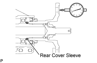
Using a dial indicator, measure the output shaft end play. Then, choose from the 15 sleeve thicknesses in the table so that the measured value will be within the standard range.
Standard end play 0.21 to 0.36 mm (0.00827 to 0.0142 in.) Sleeve Thickness Mark Thickness 02 1.725 to 1.775 mm (0.0679 to 0.0699 in.) 03 1.775 to 1.825 mm (0.0699 to 0.0719 in.) 04 1.825 to 1.875 mm (0.0719 to 0.0738 in.) 05 1.875 to 1.925 mm (0.0738 to 0.0758 in.) 06 1.925 to 1.975 mm (0.0758 to 0.0778 in.) 07 1.975 to 2.025 mm (0.0778 to 0.0797 in.) 08 2.025 to 2.075 mm (0.0797 to 0.0817 in.) 09 2.075 to 2.125 mm (0.0817 to 0.0837 in.) 10 2.125 to 2.175 mm (0.0837 to 0.0856 in.) 11 2.175 to 2.225 mm (0.0856 to 0.0876 in.) 12 2.225 to 2.275 mm (0.0876 to 0.0896 in.) 13 2.275 to 2.325 mm (0.0896 to 0.0915 in.) 14 2.325 to 2.375 mm (0.0915 to 0.0935 in.) 15 2.375 to 2.425 mm (0.0935 to 0.0955 in.) 16 2.425 to 2.475 mm (0.0955 to 0.0974 in.) -
Temporarily remove the lock nut, flange yoke, 2 spacers and sleeve, attach the selected sleeve and restore the flange yoke.
-
Using a chisel and hammer, securely stake the nut.
-
-
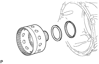
INSTALL REAR PLANETARY GEAR ASSEMBLY
-
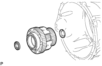
Install the thrust bearing race, rear planetary gear assembly and thrust needle roller bearing to the transmission case.
Standard Bearing and Race Diameter Item Inside Outside Race 31.5 mm (1.24 in.) 53.0 mm (2.09 in.) Bearing 31.0 mm (1.22 in.) 53.1 mm (2.09 in.) Note
-
Before installing the rear planetary gear, apply ATF to its bushing. After the installation, check that the rear planetary gear rotates smoothly.
-
Use a small amount of MP grease to secure the thrust bearing and thrust bearing race in place.
-
-
-
INSTALL REAR PLANETARY SUN GEAR ASSEMBLY
-
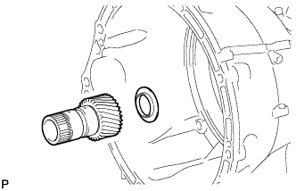
Install the thrust bearing race and rear planetary sun gear to the transmission case.
Standard Bearing Race Diameter Item Inside Outside Race 30.0 mm (1.18 in.) 49.9 mm (1.96 in.) Note
-
Before installing the sun gear, apply ATF to the contact surfaces inside the sun gear. After the installation, check that the sun gear rotates smoothly.
-
Use a small amount of MP grease to secure the thrust bearing race in place.
-
-
-
INSTALL NO. 2 BRAKE DISC SET
-
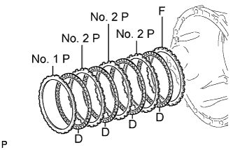
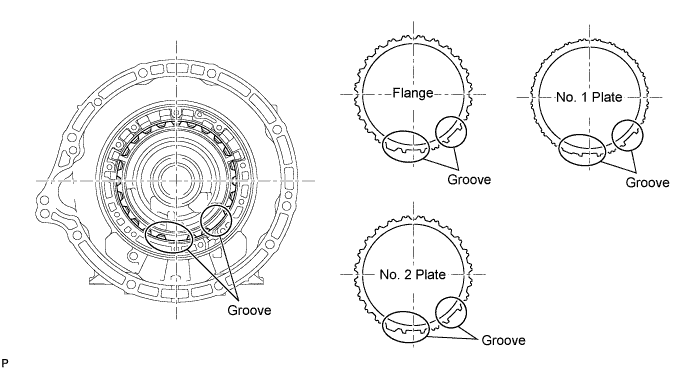
Install the selected flange, 4 discs, 3 No. 2 plates and No. 1 plate.
Install in order F - D - No. 2 P - D - No. 2 P - D - No. 2 P - D - No. 1 P Tech Tips
F = Flange
D = Disc
P = Plate
Tech Tips
Assemble the transmission case, flanges and plates by aligning their grooves as shown in the following illustration.
Note
Before assembling new discs, soak them in ATF for at least 2 hours.
-
-
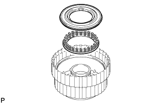
INSTALL NO. 1 ONE-WAY CLUTCH
-
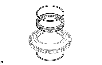
Install the No. 1 one-way clutch to the one-way clutch outer race with the 2 snap rings.
Note
Make sure to install the one-way clutch in the correct direction.
-
-
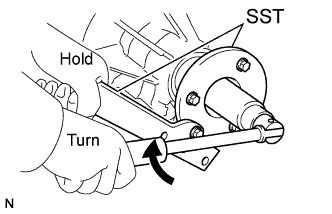
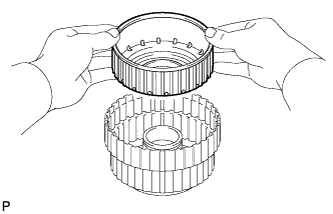
INSPECT NO. 1 ONE-WAY CLUTCH
-
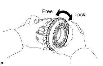
Set the one-way clutch onto the rear planetary gear.
-
Hold the rear planetary gear assembly and turn the one-way clutch.
-
Check that the one-way clutch turns freely counterclockwise and locks when turned clockwise.
If there is a problem with the No. 1 one-way clutch, replace it.
-
-
INSTALL ONE-WAY CLUTCH OUTER RACE WITH NO. 1 ONE-WAY CLUTCH
-
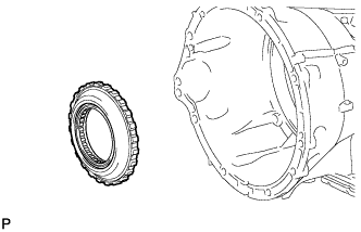
Install the one-way clutch outer race with No. 1 one-way clutch to the transmission case.
-
Using SST, install the snap ring to the transmission case.
- SST
- 09350-30020 ( 09350-07060 )
Note
-
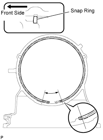
Install the snap ring so that its tapered face will be facing the front side of the transmission case.
-
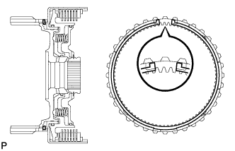
Install the snap ring so that its end gap will be within the range shown in the illustration.
-
-
INSTALL SUN GEAR INPUT DRUM SUB-ASSEMBLY
-
Install the thrust bearing race, thrust needle roller bearing and sun gear input drum.
Standard Bearing and Race Diameter Item Inside Outside Race 72.7 mm (2.86 in.) 89.2 mm (3.51 in.) Bearing 71.9 mm (2.83 in.) 85.6 mm (3.37 in.) Note
-
Before installing the sun gear input drum, apply ATF to the contact surfaces inside the sun gear input drum. After the installation, check that the sun gear input drum rotates smoothly.
-
Use a small amount of MP grease to secure the thrust bearing and thrust bearing race in place.
-
-
-
INSTALL FORWARD CLUTCH PISTON
-
Coat 2 new O-rings with ATF, and install them to the forward clutch piston.
-
Install the forward clutch piston to the forward clutch drum.
-
Coat a new O-ring with ATF, and install it to the No. 1 clutch balancer.
-
Install the forward clutch return spring sub-assembly and No. 1 clutch balancer to the forward clutch drum.
-
Place SST on the No. 1 clutch balancer, and compress the clutch balancer with a press.
- SST
- 09380-50010
-
Using SST, install the snap ring.
- SST
- 09350-30020 ( 09350-07070 )
Note
-
Be sure that the end gap of the snap ring is not aligned with the spring retainer claw.
-
Stop pressing when the balancer is lowered to the place 1 to 2 mm (0.0394 to 0.0787 in.) from the snap ring groove to prevent spring seat deformation.
-
Do not expand the snap ring excessively.
-
-
INSTALL FORWARD MULTIPLE CLUTCH DISC SET
-
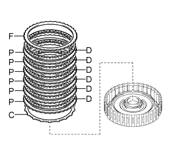
Install the cushion plate, 6 plates, 6 discs and flange to the forward clutch drum.
Install in order C - P - D - P - D - P - D - P - D - P - D - P - D - F Tech Tips
C = Cushion plate
P = Plate
D = Disc
F = Flange
Note
-
Assemble the cushion plate by facing its marked side towards the plates.
-
Before assembling new discs, soak them in ATF for at least 2 hours.
-
-
Temporarily install the snap ring.
-
Temporarily assemble the front planetary gear assembly to the forward clutch assembly.
-
Using a dial indicator, measure the distance (distance A) the clutch flange moves at both ends while blowing compressed air (196 kPa, 2.0 kgf*cm, 28 psi) from the oil hole as shown in the illustration. Then choose from the 9 flange thicknesses in the table so that the measured value will be within the standard range.
Standard 0.90 to 1.20 mm (0.0354 to 0.0472 in.) Flange Thickness Mark Thickness 0 4.35 to 4.45 mm (0.171 to 0.175 in.) 1 4.45 to 4.55 mm (0.175 to 0.179 in.) 2 4.55 to 4.65 mm (0.179 to 0.183 in.) 3 4.65 to 4.75 mm (0.183 to 0.187 in.) 4 4.75 to 4.85 mm (0.187 to 0.191 in.) 5 4.85 to 4.95 mm (0.191 to 0.195 in.) 6 4.95 to 5.05 mm (0.195 to 0.199 in.) 7 5.05 to 5.15 mm (0.199 to 0.203 in.) 8 5.15 to 5.25 mm (0.203 to 0.207 in.) -
Temporarily remove the snap ring, attach the selected flange and restore the snap ring.
-
Remove the front planetary gear assembly.
-
-
INSTALL FRONT PLANETARY RING GEAR
-
Install the snap ring to the forward clutch drum groove.
-
Using needle-nose pliers, attach the snap ring to install the front planetary ring gear to the forward multiple clutch disc.
Note
Check that the snap ring is securely fit into the groove by looking through the ring gear slots on both sides.
-
-
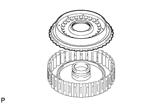
INSTALL MULTIPLE DISC CLUTCH HUB
-
Install the thrust needle roller bearing, thrust bearing race and multiple disc clutch hub to the forward clutch assembly.
Standard Bearing and Race Diameter Item Inside Outside Bearing 34.5 mm (1.36 in.) 49.4 mm (1.94 in.) Race 36.6 mm (1.44 in.) 51.9 mm (2.04 in.) Note
Use a small amount of MP grease to secure the thrust bearing and thrust bearing race in place.
-
-
INSTALL FORWARD CLUTCH ASSEMBLY WITH FRONT PLANETARY RING GEAR AND MULTIPLE DISC CLUTCH HUB
-
Install the thrust bearing race, thrust needle roller bearing and forward clutch assembly with front planetary ring gear and multiple disc clutch hub to the transmission case.
Standard Bearing and Race Diameter Item Inside Outside Bearing 47.0 mm (1.85 in.) 61.9 mm (2.44 in.) Race 46.5 mm (1.83 in.) 60.1 mm (2.37 in.) Note
-
Before installing the sun gear input drum, apply ATF to the contact surfaces inside the sun gear input drum. After the installation, check that the sun gear input drum rotates smoothly.
-
Use a small amount of MP grease to secure the thrust bearing and thrust bearing race in place.
-
-
-
INSTALL OVERDRIVE DIRECT CLUTCH PISTON SUB-ASSEMBLY
-
Coat a new O-ring with ATF, and install it to the overdrive direct clutch drum sub-assembly.
-
Coat a new O-ring with ATF, and install it to the overdrive direct clutch piston sub-assembly.
-
Install the overdrive direct clutch piston to the overdrive direct clutch drum.
-
Coat a new O-ring with ATF, and install it to the No. 3 clutch balancer.
-
Install the overdrive clutch return spring and No. 3 clutch balancer to the overdrive direct clutch piston.
-
Place SST on the No. 3 clutch balancer, and compress the clutch balancer with a press.
- SST
- 09380-50010
-
Using SST, install the snap ring.
- SST
- 09350-30020 ( 09350-07070 )
Note
-
Be sure not to align the snap ring end gap with the spring retainer claw.
-
Stop pressing when the balancer is lowered 1 to 2 mm (0.0394 to 0.0787 in.) from the snap ring groove to prevent spring seat deformation.
-
Do not expand the snap ring excessively.
-
-
INSTALL REVERSE CLUTCH DRUM SUB-ASSEMBLY
-
Coat 3 new O-rings with ATF, and install them to the reverse clutch drum.
-
Install the reverse clutch drum to the overdrive direct clutch drum sub-assembly.
-
-
INSTALL REVERSE CLUTCH PISTON
-
Coat a new O-ring with ATF, and install it to the reverse clutch piston.
-
Install the reverse clutch piston to the reverse clutch drum.
-
Install the reverse clutch return spring and reverse clutch balancer to the reverse clutch drum.
-
Place SST on the reverse clutch balancer, and compress the clutch balancer with a press.
- SST
- 09380-50010
-
Using SST, install the snap ring.
- SST
- 09350-30020 ( 09350-07070 )
Note
-
Be sure not to align the snap ring end gap with the spring retainer claw.
-
Stop pressing when the balancer is lowered 1 to 2 mm (0.0394 to 0.0787 in.) from the snap ring groove to prevent spring seat deformation.
-
Do not expand the snap ring excessively.
-
-
INSTALL REVERSE CLUTCH DISC SET
-
Install the cushion plate, 5 plates, 5 discs and flange to the No. 2 reverse clutch drum.
Install in order C - P - D - P - D - P - D - P - D - P - D - F Tech Tips
C = Cushion plate
P = Plate
D = Disc
F = Flange
Note
-
Assemble the cushion plate by facing its marked side towards the plates.
-
Before assembling new discs, soak them in ATF for at least 2 hours.
-
-
Temporarily install the snap ring.
-
Place the oil pump onto the torque converter clutch, and then place the clutch drum and input shaft onto the oil pump.
-
Using a dial indicator, measure the distance (distance A) the clutch flange moves at both ends while blowing compressed air (196 kPa, 2.0 kgf/cm2, 28 psi) from the oil hole as shown in the illustration. Then choose from the 9 flange thicknesses in the table so that the measured value will be within the standard range.
Standard 0.75 to 1.05 mm (0.0295 to 0.0413 in.) Flange Thickness Mark Thickness 0 2.95 to 3.05 mm (0.116 to 0.120 in.) 1 3.05 to 3.15 mm (0.120 to 0.124 in.) 2 3.15 to 3.25 mm (0.124 to 0.128 in.) 3 3.25 to 3.35 mm (0.128 to 0.132 in.) 4 3.35 to 3.45 mm (0.132 to 0.136 in.) 5 3.45 to 3.55 mm (0.136 to 0.140 in.) 6 3.55 to 3.65 mm (0.140 to 0.144 in.) 7 3.65 to 3.75 mm (0.144 to 0.148 in.) 8 3.75 to 3.85 mm (0.148 to 0.152 in.) -
Temporarily remove the snap ring, attach the selected flange and reinstall the snap ring.
-
-
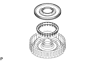
INSTALL OVERDRIVE CLUTCH DISC SET
-
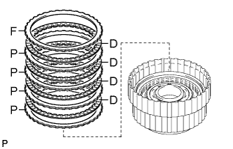
Install the 4 plates, 4 discs and flange to the overdrive direct clutch drum.
Install in order P - D - P - D - P - D - P - D - F Tech Tips
P = Plate
D = Disc
F = Flange
Note
Before assembling new discs, soak them in ATF for at least 2 hours.
-
Temporarily install the snap ring.
-
Using a dial indicator, measure the distance (distance A) the clutch flange moves at both ends while blowing compressed air (196 kPa, 2.0 kgf/cm2, 28 psi) from the oil hole as shown in the illustration. Then choose from the 9 flange thicknesses in the table so that the measured value will be within the standard range.
Standard 0.6 to 0.9 mm (0.0236 to 0.0354 in.) Flange Thickness Mark Thickness 0 3.95 to 4.05 mm (0.156 to 0.159 in.) 1 4.05 to 4.15 mm (0.159 to 0.163 in.) 2 4.15 to 4.25 mm (0.163 to 0.167 in.) 3 4.25 to 4.35 mm (0.167 to 0.171 in.) 4 4.35 to 4.45 mm (0.171 to 0.175 in.) 5 4.45 to 4.55 mm (0.175 to 0.179 in.) 6 4.55 to 4.65 mm (0.179 to 0.183 in.) -
Temporarily remove the snap ring, attach the selected flange and reinstall the snap ring.
-
-
INSTALL FRONT PLANETARY GEAR ASSEMBLY
-
Install the front planetary sun gear to the front planetary gear.
-
Coat 2 new oil seal rings with ATF, and install them to the planetary gear.
Note
Do not expand the ring ends excessively.
-
Coat 3 new oil seal rings with ATF, and install them to the planetary gear.
Note
Do not expand the ring ends excessively.
-
Install the clutch drum thrust washer to the planetary gear.
Note
Use a small amount of MP grease to secure the thrust washer in place.
-
Assemble the front planetary gear assembly with the front planetary sun gear to the overdrive and reverse clutch disc assembly.
-
-
SELECT NO. 1 BRAKE FLANGE
-
Measure length A (from the step of the oil pump installation surface of the transmission case to the step of the No. 1 brake flange installation surface) in the illustration.*1
Standard 59.77 to 60.03 mm (2.35 to 2.36 in.) -
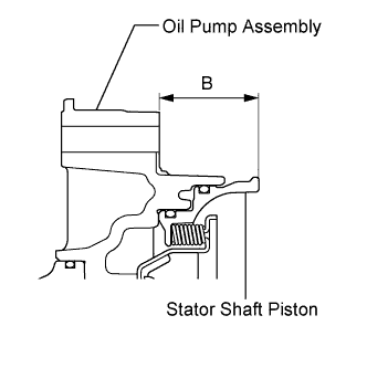
Measure length B (from the flange face of the oil pump assembly to the tip of the stator shaft piston) in the illustration.*2
Standard 34.636 to 34.964 mm (1.36 to 1.38 in.) -
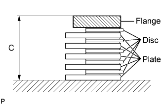
Assemble the 5 brake plates, 5 brake discs, and brake flange, and measure length C in the illustration.*3
Standard 23.84 to 24.36 mm (0.939 to 0.959 in.) -
Choose a No. 1 brake flange from the table so that the value of measured length A minus lengths B and C (from steps *1, *2, *3) will be 0.75 to 1.05 mm (0.0295 to 0.0413 in.).
Flange Thickness Mark Thickness 0 4.45 to 4.55 mm (0.175 to 0.179 in.) 1 4.55 to 4.65 mm (0.179 to 0.183 in.) 2 4.65 to 4.75 mm (0.183 to 0.187 in.) 3 4.75 to 4.85 mm (0.187 to 0.191 in.) 4 4.85 to 4.95 mm (0.191 to 0.195 in.) 5 4.95 to 5.05 mm (0.195 to 0.199 in.) 6 5.05 to 5.15 mm (0.199 to 0.203 in.) 7 5.15 to 5.25 mm (0.203 to 0.207 in.) 8 5.25 to 5.35 mm (0.207 to 0.211 in.)
-
-
INSTALL OVERDRIVE AND REVERSE CLUTCH DISC WITH FRONT PLANETARY GEAR ASSEMBLY
-
Install the thrust bearing race, thrust needle roller bearing, overdrive and reverse multiple disc clutch assembly with front planetary gear assembly to the transmission case.
Standard Bearing and Race Diameter Item Inside Outside Race 44.0 mm (1.73 in.) 62.0 mm (2.44 in.) Bearing 36.2 mm (1.43 in.) 58.2 mm (2.29 in.) Note
-
Before installing the sun gear input drum, apply ATF to the contact surfaces inside the sun gear input drum. After the installation, check that the sun gear input drum rotates smoothly.
-
Use a small amount of MP grease to secure the thrust bearing and thrust bearing race in place.
-
-
-
INSTALL NO. 1 BRAKE DISC SET
-
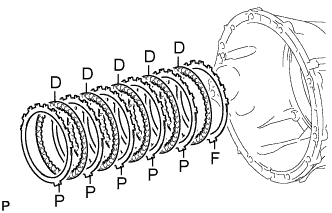
Install the selected flange, 5 discs and 5 plates to the transmission case.
Install in order F - D - P - D - P - D - P - D - P - D - P Tech Tips
F = Flange
D = Disc
P = Plate
Note
Before assembling new discs, soak them in ATF for at least 2 hours.
-
-
INSTALL OIL PUMP ASSEMBLY
-
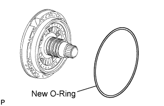
Coat a new O-ring with ATF, and install it to the oil pump.
-
Place the oil pump through the input shaft, and align the bolt holes of the oil pump with the transmission case.
-
Hold the input shaft, and lightly press the oil pump body to slide the oil seal rings into the No. 3 clutch drum.
-
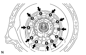
Install the 11 bolts.
- Torque:
- 21 N*m { 214 kgf*cm, 15 ft.*lbf }
Note
-
Make sure to apply seal packing to the flanges of the bolts.
Seal packing Toyota Genuine Seal Packing 1281, Three Bond 1281 or equivalent -
Do not allow seal packing to contact the bolt threads.
-
During installation, do not allow oil to contact the bolts or the surface of the oil pump body.
-
-
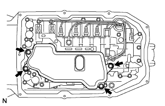
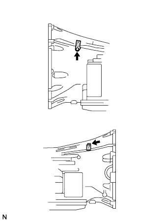
INSPECT INDIVIDUAL PISTON OPERATION
-
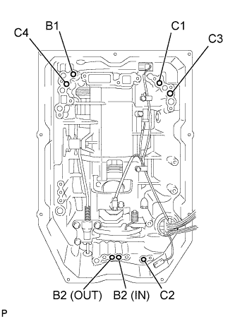
Check for operating sounds while applying compressed air into the oil holes indicated in the illustration.
Tech Tips
C1 = Forward multiple clutch
C2 = No. 2 clutch
C3 = No. 3 clutch
C4 = Reverse clutch
B1 = No. 1 brake
B2 = No. 2 brake
-
-
INSTALL MANUAL VALVE LEVER SHAFT OIL SEAL
-
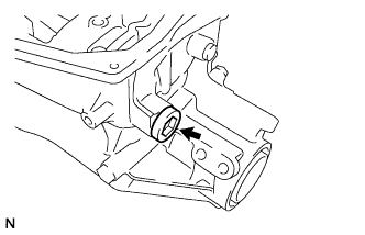
Using SST and a hammer, tap in a new oil seal.
- SST
- 09350-30020 ( 09350-07110 )
Standard depth -0.3 to 0.3 mm (-0.0118 to 0.0118 in.) -
Coat the lip of the oil seal with MP grease.
-
-
INSTALL MANUAL VALVE LEVER SUB-ASSEMBLY
-
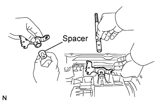
Install a new spacer to the manual valve lever.
-
Install the manual valve lever shaft to the transmission case through the manual valve lever.
-
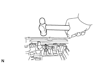
Using a hammer, tap in a new spring pin.
-
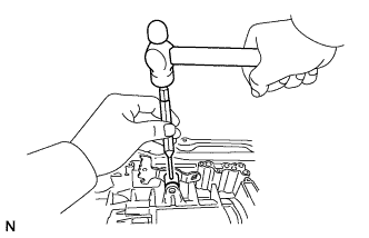
Align the manual valve lever indentation with the spacer hole, and stake them together with a punch.
-
Make sure that the shaft rotates smoothly.
-
-
INSTALL PARKING LOCK PAWL SHAFT
-
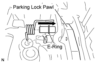
Install the E-ring to the shaft.
-
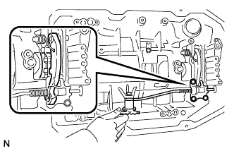
Install the parking lock pawl, shaft and spring.
-
-
INSTALL PARKING LOCK ROD SUB-ASSEMBLY
-
Connect the parking lock rod to the manual valve lever.
-
-
INSTALL PARKING LOCK PAWL BRACKET
-
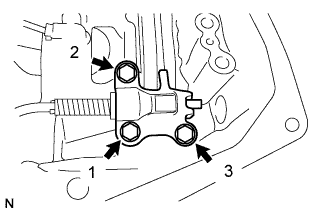
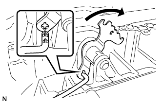
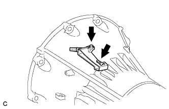
Place the parking lock pawl bracket onto the transmission case. Loosely install the 3 bolts, and then tighten them in the order shown in the illustration.
- Torque:
- 18 N*m { 184 kgf*cm, 13 ft.*lbf }
-
Shift the manual valve lever to the P position, and confirm that the output shaft is locked correctly by the lock pawl.
-
-
INSTALL AUTOMATIC TRANSMISSION CASE PLUG
-
Coat a new O-ring with ATF, and install it to the case plug.
-
Install the case plug to the transmission case.
- Torque:
- 80 N*m { 816 kgf*cm, 59 ft.*lbf }
-
-
INSTALL SPEED SENSOR
-
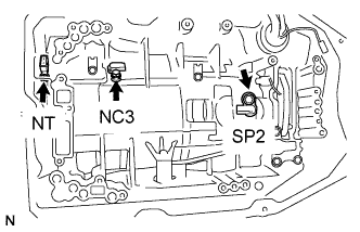
Coat a new O-ring with ATF and install it to the speed sensor NT .
-
Using a T30 ''TORX'' wrench, install the sensor NT with the bolt.
- Torque:
- 6.8 N*m { 69 kgf*cm, 60 in.*lbf }
-
Install the 2 speed sensors SP2 and NC3 with the 2 bolts.
- Torque:
- 5.4 N*m { 55 kgf*cm, 48 in.*lbf }
-
-
INSTALL TRANSMISSION WIRE
-
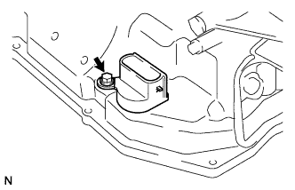
Coat a new O-ring with ATF and install it to the transmission wire connector.
-
Install the transmission wire.
-
Install the bolt.
- Torque:
- 5.4 N*m { 55 kgf*cm, 48 in.*lbf }
-
Connect the 3 speed sensor connectors.
-
-
INSTALL CHECK BALL BODY
-
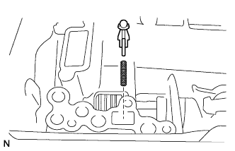
Install the spring and check ball body.
-
-
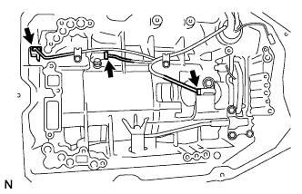
INSTALL TRANSMISSION VALVE BODY ASSEMBLY
-
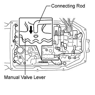
Align the groove of the manual valve lever sub-assembly with the manual valve connecting rod and install the connecting rod.
-
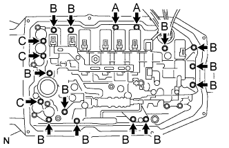
Install the 17 bolts.
- Torque:
- 11 N*m { 112 kgf*cm, 8 ft.*lbf }
Tech Tips
Each bolt length is indicated below.
Bolt length 21 mm (0.827 in.) for bolt A 31 mm (1.22 in.) for bolt B 64 mm (2.52 in.) for bolt C -
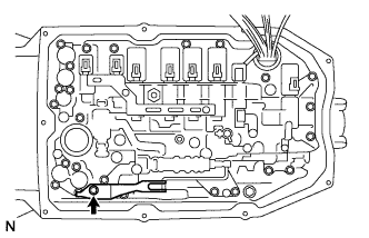
Install the detent spring and detent spring cover with the bolt.
- Torque:
- 10 N*m { 102 kgf*cm, 7 ft.*lbf }
Note
Make sure to install the detent spring so that its roller is perpendicular to the center of the manual valve lever sub-assembly.
-
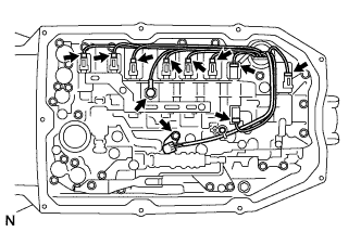
Connect the 9 connectors to the solenoid valves.
-
Connect the oil pressure switch connector.
-
Coat a new O-ring with ATF and install it to the ATF temperature sensor.
-
Install the ATF temperature sensor and lock plate with the bolt.
- Torque:
- 10 N*m { 102 kgf*cm, 7 ft.*lbf }
-
-
INSTALL VALVE BODY OIL STRAINER ASSEMBLY
-
Coat a new O-ring with ATF and install it to the oil strainer.
Note
Ensure that the O-ring is not twisted or pinched.
-
Install the oil strainer to the valve body with the 4 bolts.
- Torque:
- 11 N*m { 112 kgf*cm, 8 ft.*lbf }
-
-
INSTALL AUTOMATIC TRANSMISSION OIL PAN SUB-ASSEMBLY
-
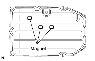
Install the 3 magnets to the oil pan.
-
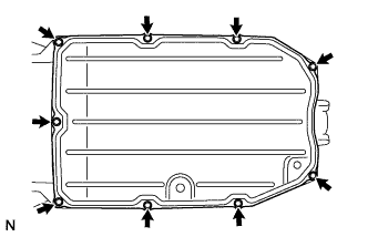
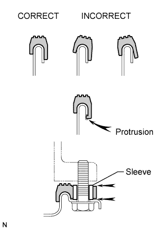
Install a new gasket and the oil pan to the transmission case with the 9 bolts.
- Torque:
- 7.4 N*m { 75 kgf*cm, 65 in.*lbf }
Note
-
Make sure that there is no oil or foreign matter on the gasket seal surface or oil pan contact surface.
-
Install the gasket so that there is no movement in the gasket, and that the entire seal surface is level.
-
Make sure that the 9 gasket drop prevention protrusions are set on the oil pan.
-
When tightening the oil pan, make sure that the gasket is not pinched between the gasket tightening area's sleeve and the transmission's seal surface.
-
-
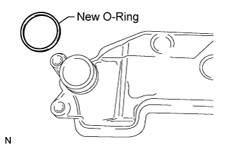
INSTALL AUTOMATIC TRANSMISSION BREATHER TUBE
-
Install the O-ring to the automatic transmission breather tube.
-
Install the automatic transmission breather tube with the bolt.
- Torque:
- 5.4 N*m { 55 kgf*cm, 48 in.*lbf }
-
-
INSTALL OIL COOLER TUBE UNION
-
Coat 2 new O-rings with ATF, and install them to the 2 unions.
-
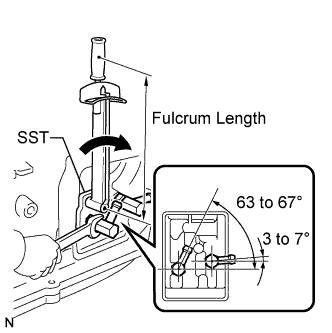
Using SST, install the 2 unions as shown in the illustration.
- SST
- 09268-78010
- Torque:
- without SST
- 29 N*m { 296 kgf*cm, 21 ft.*lbf }
- with SST
- 24 N*m { 248 kgf*cm, 18 ft.*lbf }
Note
Use a torque wrench with a fulcrum length of 180 mm (7.09 in.).
-
-
INSTALL PARK/NEUTRAL POSITION SWITCH ASSEMBLY
-
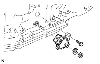
Install the park/neutral position switch assembly onto the manual valve lever shaft, and temporarily install the bolt.
-
Install a new lock washer with the nut.
- Torque:
- 6.9 N*m { 70 kgf*cm, 61 in.*lbf }
-
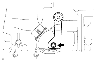
Temporarily install the control shaft lever RH.
-
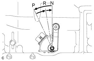
Turn the control shaft lever RH counterclockwise until it stops, and turn it clockwise 2 notches to set it to the N position.
-
Remove the control shaft lever RH.
-
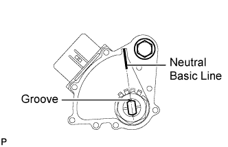
Align the groove with the neutral basic line.
-
Hold the switch in this position and tighten the bolt.
- Torque:
- 13 N*m { 130 kgf*cm, 9 ft.*lbf }
-
Using a screwdriver, bend the tabs of the lock washer.
Tech Tips
Bend at least 2 washer tabs.
-
-
INSTALL TRANSMISSION CONTROL SHAFT LEVER RH
-
Install the transmission control shaft lever RH with the spring washer and nut.
- Torque:
- 16 N*m { 160 kgf*cm, 12 ft.*lbf }
-
-
INSTALL HARNESS BRACKET
-
Install the 2 harness brackets with the 2 bolts.
- Torque:
- 10 N*m { 102 kgf*cm, 8 ft.*lbf }
-