AUTOMATIC TRANSMISSION UNIT DISASSEMBLY

-
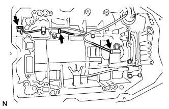
REMOVE HARNESS BRACKET
-
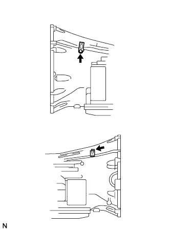
Remove the 2 bolts and harness brackets.
-
-
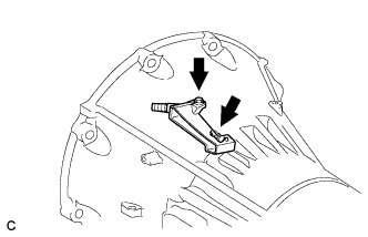
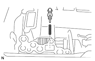
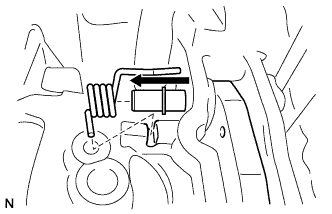
REMOVE TRANSMISSION CONTROL SHAFT LEVER RH
-
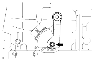
Remove the nut, spring washer and transmission control shaft lever RH.
-
-
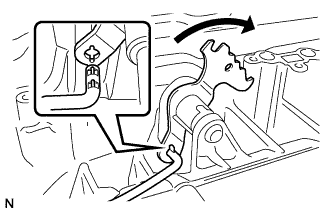
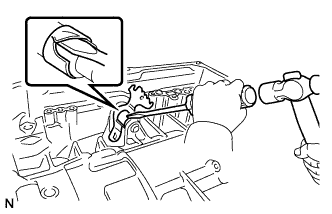
REMOVE PARK/NEUTRAL POSITION SWITCH ASSEMBLY
-
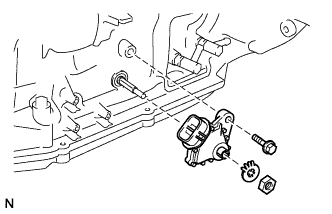
Using a screwdriver, bend the tabs of the lock washer.
-
Remove the nut and lock washer.
-
Remove the bolt and park/neutral position switch assembly.
-
-
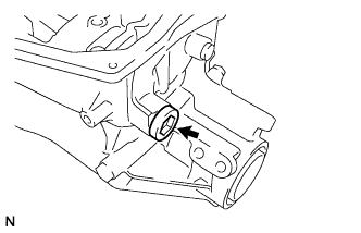
REMOVE OIL COOLER TUBE UNION
-
Remove the 2 oil cooler tube unions.
-
Remove the 2 O-rings from the 2 oil cooler tube unions.
-
-
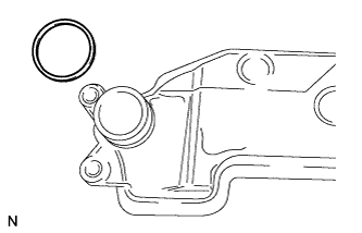
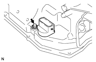
REMOVE AUTOMATIC TRANSMISSION BREATHER TUBE
-
Remove the bolt and automatic transmission breather tube.
-
Remove the O-ring from the automatic transmission breather tube.
-
-
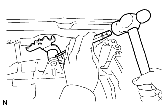
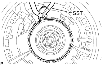
REMOVE AUTOMATIC TRANSMISSION FLANGE YOKE ASSEMBLY
-
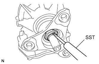
Using SST and a hammer, loosen the staked part of the nut.
- SST
- 09930-00010
-
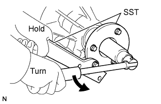
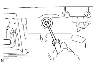
Using SST and a 30 mm socket wrench, remove the nut.
- SST
- 09330-00021
- 09950-30012 ( 09955-03040 )
-
Remove SST.
-
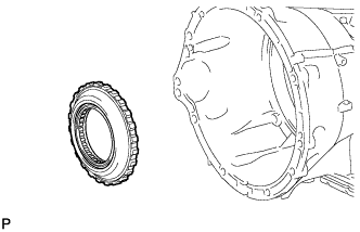
Tap the flange yoke with a plastic-faced hammer to remove it.
-
Remove the 2 rear No. 1 output shaft bearing spacers and rear cover sleeve.
-
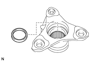
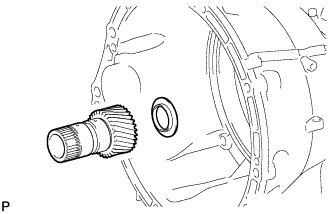
Using a screwdriver, pry out the oil seal from the flange yoke.
-
-
REMOVE AUTOMATIC TRANSMISSION OIL PAN SUB-ASSEMBLY
Note
Do not turn the transmission over as this will contaminate the valve body with foreign matter located at the bottom of the pan.
-
Remove the overflow plug and gasket.
-
Remove the drain plug and gasket.
-
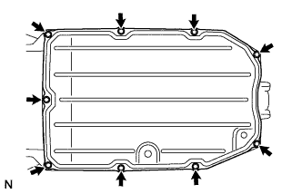
Remove the 9 bolts, oil pan and gasket.
-
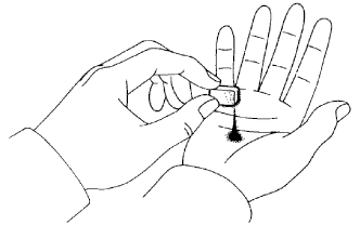
Examine the particles in the pan.
-
Remove the magnets from the oil pan. Use the removed magnets to collect any steel chips. Look carefully at the chips and particles in the pan and on the magnet to anticipate the type of wear which might be found in the transmission.
Steel (magnetic): bearing, gear and plate wear
Brass (non-magnetic): bush wear
-
-
-
REMOVE VALVE BODY OIL STRAINER ASSEMBLY
-
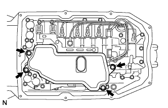
Remove the 4 bolts and valve body oil strainer from the valve body.
-
Remove the O-ring from the valve body oil strainer.
-
-
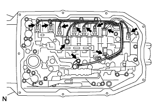
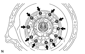
REMOVE TRANSMISSION VALVE BODY ASSEMBLY
-
Remove the bolt, lock plate and ATF temperature sensor.
-
Remove the O-ring from the ATF temperature sensor.
-
Disconnect the oil pressure switch connector.
-
Disconnect the 9 connectors from the solenoid valves.
-
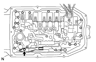
Remove the bolt, detent spring cover and detent spring.
-
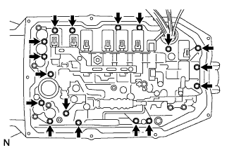
Remove the 17 bolts.
-
Remove the valve body.
-
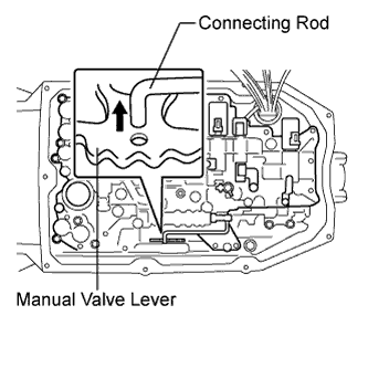
Disconnect the manual valve connecting rod from the manual valve lever sub-assembly.
-
-
REMOVE CHECK BALL BODY
-
Remove the check ball body and spring.
-
-
REMOVE TRANSMISSION WIRE
-
Disconnect the 3 connectors from the 3 speed sensors.
-
Remove the bolt and pull out the transmission wire.
-
Remove the O-ring from the transmission wire connector.
-
-
REMOVE SPEED SENSOR
-
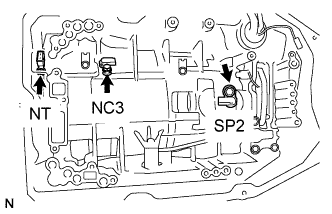
Remove the 2 bolts and 2 speed sensors NC3 and SP2.
-
Using a T30 ''TORX'' wrench, remove the bolt and speed sensor NT.
-
Remove the O-ring from the speed sensor NT.
-
-
REMOVE AUTOMATIC TRANSMISSION CASE PLUG
-
Remove the plug and O-ring.
-
-
REMOVE PARKING LOCK PAWL BRACKET
-
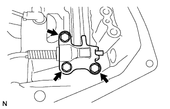
Remove the 3 bolts and parking lock pawl bracket.
-
-
REMOVE PARKING LOCK ROD SUB-ASSEMBLY
-
Disconnect the parking lock rod from the manual valve lever.
-
-
REMOVE PARKING LOCK PAWL SHAFT
-
Pull out the parking lock pawl shaft from the front side, then remove the lock pawl and spring.
-
Remove the E-ring from the shaft.
-
-
REMOVE MANUAL VALVE LEVER SUB-ASSEMBLY
-
Using a screwdriver and hammer, cut off the spacer and remove it from the shaft.
-
Using a pin punch and hammer, tap out the spring pin.
Tech Tips
Slowly tap out the spring pin so that it will not fall into the transmission case.
-
Pull the manual valve lever shaft out through the case, and remove the manual valve lever sub-assembly.
-
-
REMOVE MANUAL VALVE LEVER SHAFT OIL SEAL
-
Using a screwdriver, pry out the oil seal.
-
-
REMOVE OIL PUMP ASSEMBLY
-
Remove the 11 bolts from the transmission case.
-
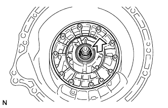
Pull out the oil pump.
Note
Do not damage the oil pump.
-
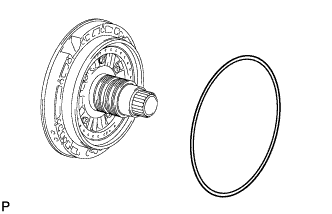
Remove the O-ring from the oil pump.
-
-
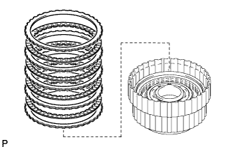
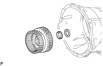
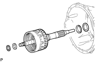
REMOVE OVERDRIVE AND REVERSE CLUTCH DISC ASSEMBLY AND FRONT PLANETARY GEAR ASSEMBLY WITH NO. 1 BRAKE DISC SET
-
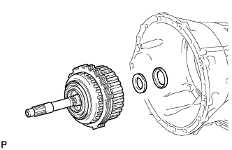
Remove the overdrive and reverse clutch disc assembly and front planetary gear with No. 1 brake disc set from the transmission case.
-
Remove the thrust needle roller bearing and race.
-
-
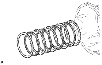
REMOVE NO. 1 BRAKE DISC SET
-
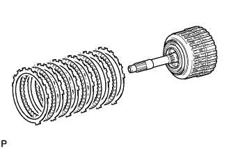
Remove the 5 plates, 5 discs and flange.
-
-
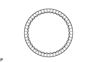
INSPECT NO. 1 BRAKE DISC
-
Replace all discs if one of the following problems is present: 1) a disc, plate or flange is worn or burnt; 2) the lining of a disc is peeled off or discolored; or 3) grooves or printed numbers have even minimal damage.
Note
Before assembling new discs, soak them in ATF for at least 2 hours.
-
-
REMOVE FRONT PLANETARY GEAR ASSEMBLY
-
Remove the front planetary gear with the front planetary sun gear from the overdrive and reverse clutch disc assembly.
-
Remove the 3 oil seal rings.
-
Remove the clutch drum thrust washer.
-
Remove the 2 clutch drum oil seal rings.
-
Remove the front planetary sun gear.
-
-
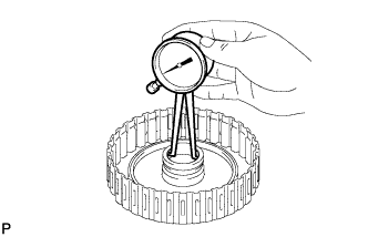
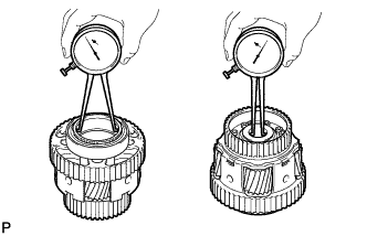
INSPECT FRONT PLANETARY GEAR ASSEMBLY
-
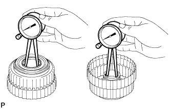
Using a feeler gauge, measure the thrust clearance of the front planetary gear pinion.
Standard clearance 0.2 to 0.6 mm (0.00787 to 0.0236 in.) If the clearance is not as specified, replace the front planetary gear assembly.
-
-
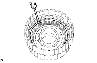
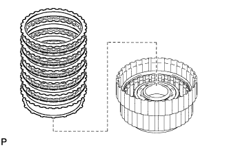
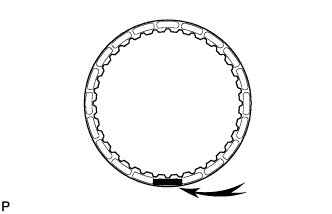
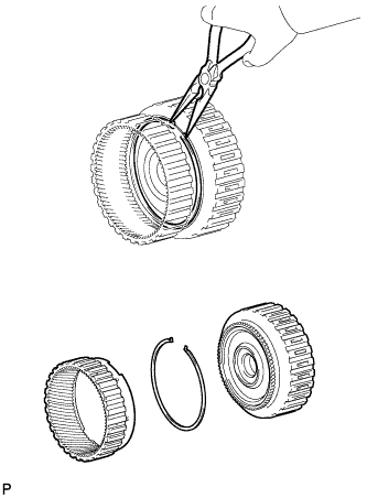
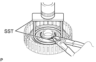
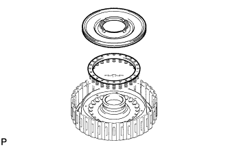
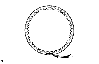
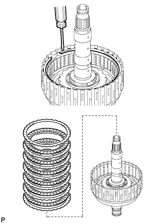
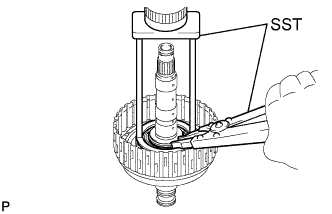
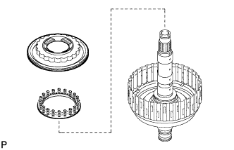
REMOVE OVERDRIVE CLUTCH DISC SET
-
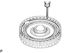
Using a screwdriver, remove the snap ring from the overdrive direct clutch drum sub-assembly.
-
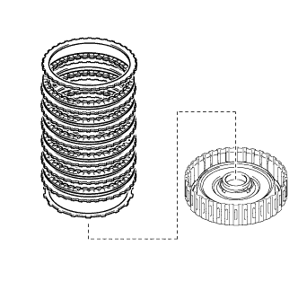
Remove the flange, 4 discs and 4 plates from the overdrive direct clutch drum sub-assembly.
-
-
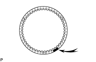
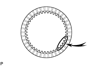
INSPECT OVERDRIVE CLUTCH DISC
-
Replace all discs if one of the following problems is present: 1) a disc, plate or flange is worn or burnt; 2) the lining of a disc is peeled off or discolored; or 3) grooves or printed numbers have even minimal damage.
Note
Before assembling new discs, soak them in ATF for at least 2 hours.
-
-
REMOVE REVERSE CLUTCH DISC SET
-
Using a screwdriver, remove the snap ring from the reverse clutch drum sub-assembly.
-
Remove the flange, 5 discs, 5 plates and cushion plate from the reverse clutch drum sub-assembly.
-
-
INSPECT REVERSE CLUTCH DISC
-
Replace all discs if one of the following problems is present: 1) a disc, plate or flange is worn or burnt; 2) the lining of a disc is peeled off or discolored; or 3) grooves or printed numbers have even minimal damage.
Note
Before assembling new discs, soak them in ATF for at least 2 hours.
-
-
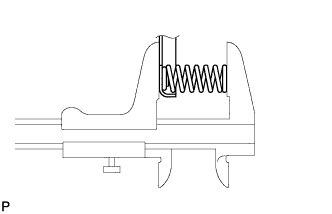
REMOVE REVERSE CLUTCH PISTON
-
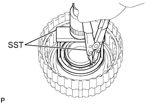
Place SST on the reverse clutch balancer, and compress the return spring with a press.
- SST
- 09380-50010
-
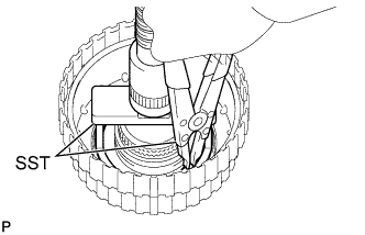
Using SST, remove the snap ring.
- SST
- 09350-30020 ( 09350-07070 )
-
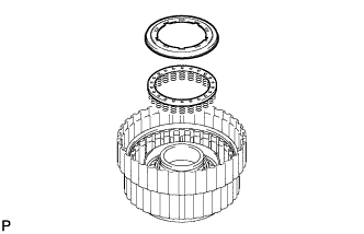
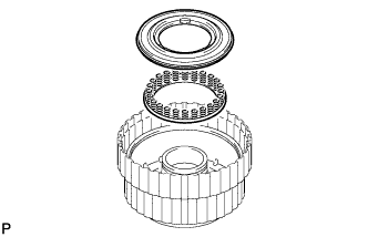
Remove the reverse clutch balancer and reverse clutch return spring from the reverse clutch drum sub-assembly.
-
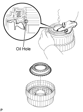
Hold the clutch piston and apply compressed air to the oil hole of the reverse clutch drum to remove the clutch piston.
-
Remove the O-ring from the reverse clutch piston.
-
-
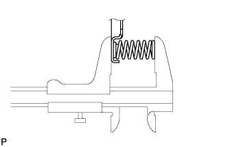
INSPECT REVERSE CLUTCH RETURN SPRING SUB-ASSEMBLY
-
Using a vernier caliper, measure the free length of the spring together with the spring seat.
Standard free length 22.21 mm (0.874 in.) If the free length is shorter than the standard free length, replace the reverse clutch return spring sub-assembly.
-
-
REMOVE REVERSE CLUTCH DRUM SUB-ASSEMBLY
-
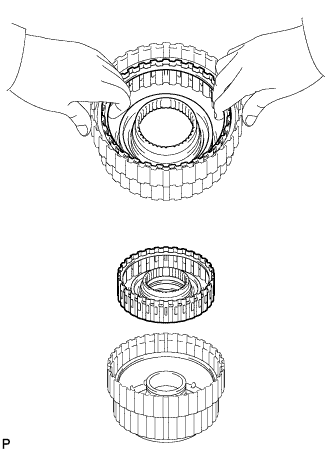
Remove the reverse clutch drum from the overdrive direct clutch drum.
Tech Tips
The reverse clutch drum is easier to remove if the hole snap ring is installed. Use the hole snap ring removed in "remove reverse clutch disc set".
-
Remove the 3 O-rings from the reverse clutch drum sub-assembly.
-
-
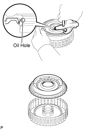
REMOVE OVERDRIVE DIRECT CLUTCH PISTON SUB-ASSEMBLY
-
Place SST on the No. 3 clutch balancer, and compress the return spring with a press.
- SST
- 09380-50010
-
Using SST, remove the snap ring.
- SST
- 09350-30020 ( 09350-07070 )
-
Remove the No. 3 clutch balancer and overdrive clutch return spring sub-assembly.
-
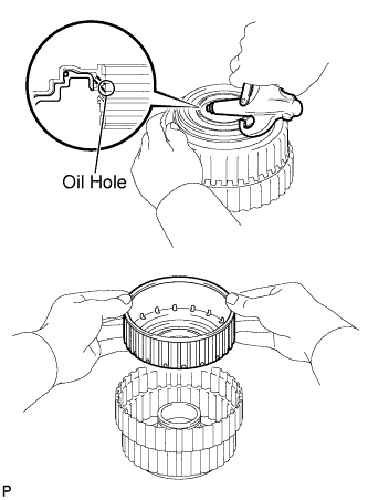
Hold the overdrive direct clutch piston and apply compressed air to the oil hole of the overdrive direct clutch drum to remove the overdrive direct clutch piston sub-assembly.
-
Remove the O-ring from the No. 3 clutch balancer.
-
Remove the O-ring from the overdrive direct clutch piston sub-assembly.
-
Remove the O-ring from the overdrive direct clutch drum sub-assembly.
-
-
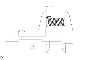
INSPECT OVERDRIVE CLUTCH RETURN SPRING SUB-ASSEMBLY
-
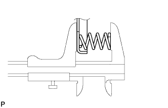
Using a vernier caliper, measure the free length of the spring together with the spring seat.
Standard free length 21.09 mm (0.830 in.) If the free length is shorter than the standard free length, replace the overdrive clutch return spring sub-assembly.
-
-
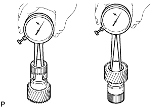
INSPECT OVERDRIVE DIRECT CLUTCH DRUM SUB-ASSEMBLY
-
Using a caliper gauge, measure the inside diameter of the overdrive direct clutch drum bush.
Standard inside diameter (Front side) 67.40 to 67.44 mm (2.65354 to 2.65511 in.) Standard inside diameter (Rear side) 55.62 to 55.64 mm (2.18976 to 2.19054 in.) If the inside diameter is not as specified, replace the overdrive direct clutch drum sub-assembly.
-
-
REMOVE FORWARD MULTIPLE CLUTCH DISC ASSEMBLY WITH FRONT PLANETARY RING GEAR
-
Remove the forward multiple clutch disc assembly with front planetary ring gear, thrust needle roller bearing and race from the transmission case.
-
Using needle-nose pliers, detach the snap ring and remove the front planetary ring gear and snap ring from the forward multiple clutch disc assembly.
-
-
REMOVE FORWARD MULTIPLE CLUTCH DISC SET
-
Using a screwdriver, remove the snap ring.
-
Remove the flange, 6 discs, 6 plates and cushion plate.
-
-
INSPECT FORWARD MULTIPLE CLUTCH DISC
-
Replace all discs if one of the following problems is present: 1) a disc, plate or flange is worn or burnt; 2) the lining of a disc is peeled off or discolored; or 3) grooves or printed numbers have even minimal damage.
Note
Before assembling new discs, soak them in ATF for at least 2 hours.
-
-
REMOVE FORWARD CLUTCH PISTON
-
Place SST on the No. 1 clutch balancer, and compress the return spring with a press.
- SST
- 09380-50010
-
Using SST, remove the snap ring.
- SST
- 09350-30020 ( 09350-07070 )
-
Remove the No. 1 clutch balancer and forward clutch return spring sub-assembly from the forward clutch drum sub-assembly.
-
Remove the O-ring from the No. 1 clutch balancer.
-
Hold the forward clutch piston and apply compressed air to the oil hole of the forward clutch drum to remove the forward clutch piston.
-
Remove the 2 O-rings from the piston.
-
-
INSPECT FORWARD CLUTCH RETURN SPRING SUB-ASSEMBLY
-
Using a vernier caliper, measure the free length of the spring together with the spring seat.
Standard free length 20.82 mm (0.820 in.) If the free length is shorter than the standard free length, replace the forward clutch return spring sub-assembly.
-
-
INSPECT FORWARD CLUTCH DRUM SUB-ASSEMBLY
-
Using a caliper gauge, measure the inside diameter of the forward clutch drum bush.
Standard inside diameter 33.200 to 33.225 mm (1.30708 to 1.30807 in.) If the inside diameter is not as specified, replace the forward clutch drum sub-assembly.
-
-
REMOVE MULTIPLE DISC CLUTCH HUB
-
Remove the multiple disc clutch hub from the transmission case.
-
Remove the thrust bearing race and thrust needle roller bearing from the transmission case.
-
-
REMOVE SUN GEAR INPUT DRUM SUB-ASSEMBLY
-
Remove the sun gear input drum, thrust needle roller bearing and race from the transmission case.
-
-
INSPECT SUN GEAR INPUT DRUM SUB-ASSEMBLY
-
Using a caliper gauge, measure the inside diameter of the sun gear input drum bush.
Standard inside diameter 45.075 to 45.100 mm (1.77460 to 1.77559 in.) If the inside diameter is not as specified, replace the sun gear input drum sub-assembly.
-
-
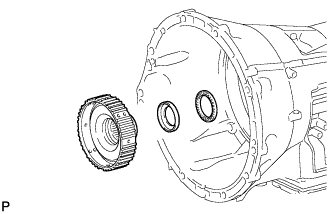
REMOVE ONE-WAY CLUTCH OUTER RACE WITH NO. 1 ONE-WAY CLUTCH
-
Using SST, remove the snap ring from the transmission case.
- SST
- 09350-30020 ( 09350-07060 )
-
Remove the one-way clutch outer race with No.1 one-way clutch.
-
-
REMOVE REAR PLANETARY SUN GEAR ASSEMBLY
-
Remove the rear planetary sun gear and thrust bearing race from the transmission case.
-
-
INSPECT REAR PLANETARY SUN GEAR ASSEMBLY
-
Using a caliper gauge, measure the inside diameter of the rear planetary sun gear bush.
Standard inside diameter 28.700 to 28.721 mm (1.12991 to 1.13075 in.) If the inside diameter is not as specified, replace the rear planetary sun gear assembly.
-
-
REMOVE REAR PLANETARY GEAR ASSEMBLY
-
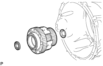
Remove the thrust needle roller bearing, rear planetary gear assembly and thrust bearing race from the transmission case.
-
-
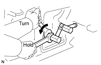
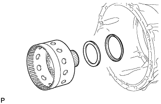
INSPECT NO. 1 ONE-WAY CLUTCH
-
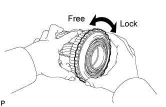
Set the one-way clutch onto the rear planetary gear.
-
Hold the rear planetary gear assembly and turn the one-way clutch.
-
Check that the one-way clutch turns freely counterclockwise and locks when turned clockwise.
If there is a problem with the No. 1 one-way clutch, replace it.
-
-
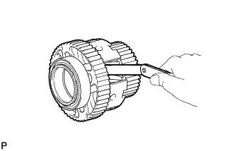
REMOVE NO. 1 ONE-WAY CLUTCH
-
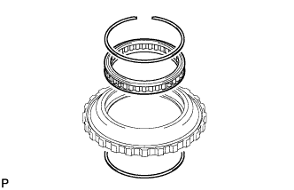
Remove the 2 snap rings and No. 1 one-way clutch from the one-way clutch outer race.
-
-
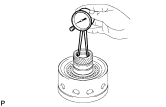
INSPECT REAR PLANETARY GEAR ASSEMBLY
-
Using a feeler gauge, measure the long and short thrust clearances of the rear planetary gear pinion.
Standard clearance 0.2 to 0.6 mm (0.00787 to 0.0236 in.) If the clearance is not as specified, replace the rear planetary gear assembly.
-
Using a caliper gauge, measure the inside diameter of the rear planetary gear bush.
Standard inside diameter (Front side) 71.60 to 71.63 mm (2.81889 to 2.82007 in.) Standard inside diameter (Rear side) 28.700 to 28.721 mm (1.12992 to 1.13075 in.) If the inside diameter is not as specified, replace the rear planetary gear assembly.
-
-
REMOVE NO. 2 BRAKE DISC SET
-
Remove the No. 1 plate, 4 discs, 3 No. 2 plates and flange.
-
-
INSPECT NO. 2 BRAKE DISC
-
Replace all discs if one of the following problems is present: 1) a disc, plate or flange is worn or burnt; 2) the lining of a disc is peeled off or discolored; or 3) grooves or printed numbers have even minimal damage.
Note
Before assembling new discs, soak them in ATF for at least 2 hours.
-
-
REMOVE DIRECT CLUTCH DRUM SUB-ASSEMBLY WITH REAR PLANETARY RING GEAR AND OUTPUT SHAFT SUB-ASSEMBLY
-
Remove the 2 thrust needle roller bearings, 2 races, direct clutch assembly with rear planetary ring gear and output shaft from the transmission case.
-
-
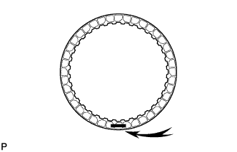
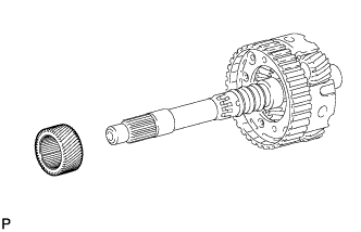
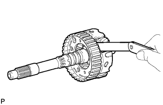
REMOVE REAR PLANETARY RING GEAR
-
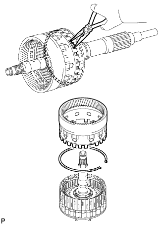
Using needle-nose pliers, detach the snap ring and disconnect the rear planetary ring gear from the output shaft sub-assembly.
-
-
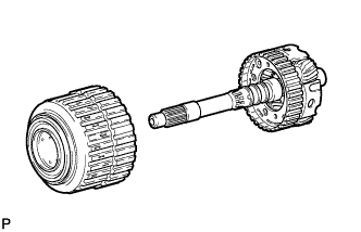
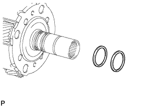
DISCONNECT DIRECT CLUTCH ASSEMBLY
-
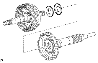
Disconnect the direct clutch drum from the output shaft and remove the thrust needle roller bearing and thrust bearing race from the output shaft.
-
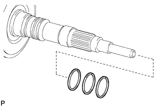
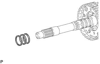
Remove the 3 clutch drum oil seal rings from the output shaft.
-
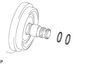
Remove the 2 clutch drum oil seal rings from the direct clutch drum.
-
-
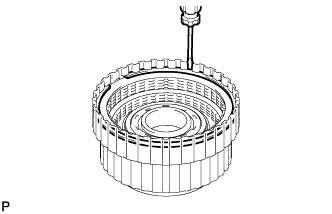
REMOVE NO. 2 CLUTCH DISC SET
-
Remove the snap ring, flange, 6 discs, and 6 plates from the direct clutch drum.
-
-
INSPECT NO. 2 CLUTCH DISC
-
Replace all discs if one of the following problems is present: 1) a disc, plate or flange is worn or burnt; 2) the lining of a disc is peeled off or discolored; or 3) grooves or printed numbers have even minimal damage.
Note
Before assembling new discs, soak them in ATF for at least 2 hours.
-
-
REMOVE DIRECT CLUTCH PISTON
-
Place SST on the No. 2 clutch balancer, and compress the return spring with a press.
- SST
- 09387-00020
-
Using SST, remove the snap ring.
- SST
- 09350-30020 ( 09350-07070 )
-
Remove the No. 2 clutch balancer and direct clutch return spring sub-assembly from the direct clutch drum.
-
Remove the O-ring from the balancer.
-
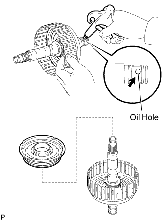
Hold the direct clutch piston and apply compressed air to the oil hole of the direct clutch drum to remove the direct clutch piston.
-
Remove the O-ring from the direct clutch piston.
-
Remove the O-ring from the direct clutch drum.
-
-
INSPECT DIRECT CLUTCH RETURN SPRING SUB-ASSEMBLY
-
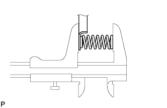
Using a vernier caliper, measure the free length of the spring together with the spring seat.
Standard free length 20.76 mm (0.817 in.) If the free length is shorter than the standard free length, replace the direct clutch return spring sub-assembly.
-
-
REMOVE NO. 2 BRAKE PISTON
-
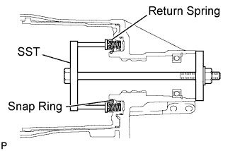
Set SST on the No. 2 brake piston return spring, tighten SST and compress the return spring.
- SST
- 09380-50010
-
Using SST, remove the snap ring and the No. 2 brake piston return spring sub-assembly.
- SST
- 09350-30020 ( 09350-07070 )
-
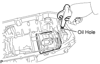
Hold the No. 2 brake piston and apply compressed air to the oil hole of the transmission case to remove the No. 2 brake piston.
-
Remove the 3 O-rings from the No. 2 brake piston.
-
-
INSPECT NO. 2 BRAKE PISTON RETURN SPRING SUB-ASSEMBLY
-
Using a vernier caliper, measure the free length of the spring together with the spring seat.
Standard free length 23.36 mm (0.920 in.) If the free length is shorter than the standard free length, replace the No. 2 brake piston return spring sub-assembly.
-
-
REMOVE BRAKE PLATE STOPPER SPRING
-
Remove the 2 brake plate stopper springs.
-
-
REMOVE REAR AUTOMATIC TRANSMISSION OIL SEAL
-
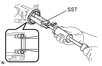
Using SST, tap out the oil seal.
- SST
- 09308-00010
-
-
REMOVE REAR OUTPUT SHAFT RADIAL BALL BEARING
-
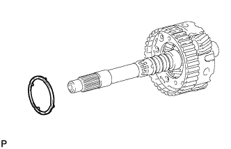
Using snap ring pliers, remove the snap ring from the transmission case.
-
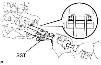
Using SST, remove the bearing.
- SST
- 09308-00010
-