AUTOMATIC TRANSMISSION ASSEMBLY INSTALLATION

-
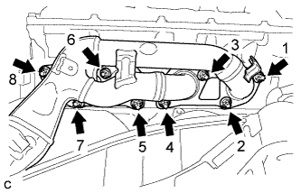
INSTALL TRANSMISSION BREATHER ASSEMBLY
-
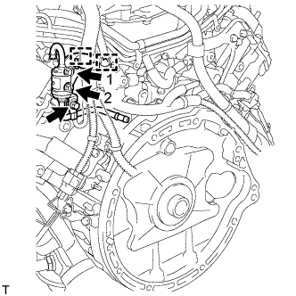
Install the 2 bolts to the transmission breather assembly in the order shown in the illustration.
- Torque:
- Bolt 1
- 7.0 N*m { 71 kgf*cm, 62 in.*lbf }
- Bolt 2
- 7.0 N*m { 71 kgf*cm, 62 in.*lbf }
Bolt Bolt Length 1 30 mm (1.18 in.) 2 14 mm (0.551 in.) Tech Tips
Be sure to install the transmission breather assembly so that the pipe is positioned between the two-way wire harness.
-
Connect the 2 wire harness clamps to the transmission breather assembly .
-
Install the bolt and ground wire to the transmission breather assembly.
- Torque:
- 10 N*m { 102 kgf*cm, 7 ft.*lbf }
-
-
INSTALL AUTOMATIC TRANSMISSION BREATHER TUBE
-
Connect the breather hose to the breather tube.
Tech Tips
Be sure to insert the breather hose to the end.
-
Install a new O-ring.
-
Coat the O-ring with ATF.
-
Install the transmission breather tube with the bolt.
- Torque:
- 5.4 N*m { 55 kgf*cm, 48 in.*lbf }
-
-
INSPECT TORQUE CONVERTER CLUTCH ASSEMBLY
-
Inspect the torque converter clutch Click here.
-
-
INSTALL TORQUE CONVERTER CLUTCH ASSEMBLY
-
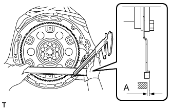
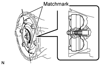
Using a vernier caliper and a straightedge, measure dimension A between the transmission and the end surface of the drive plate.
-
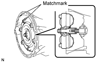
Aligning the matchmarks on the transmission case and torque converter clutch, engage the splines of the input shaft and turbine runner.
-
Engage the splines of the stator shaft and stator while turning the torque converter clutch.
Tech Tips
Turn the torque converter clutch approximately 180°.
-
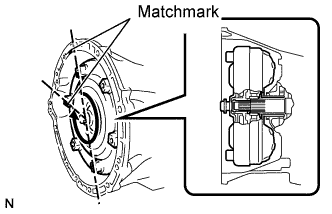
Turn the torque converter clutch and align the matchmarks on the torque converter clutch and transmission case to engage the key of the oil pump drive gear into the slot on the torque converter clutch.
Note
Do not push on the torque converter when aligning the matchmarks.
-
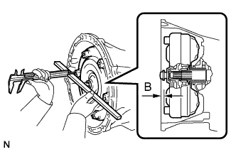
Using a vernier caliper and a straightedge, measure dimension B shown in the illustration and check that B is greater than A measured in the first step.
Standard A + 1 mm (0.04 in.) or more
-
-
INSTALL AUTOMATIC TRANSMISSION ASSEMBLY
-
Make sure that the knock pins are installed on the engine.
-
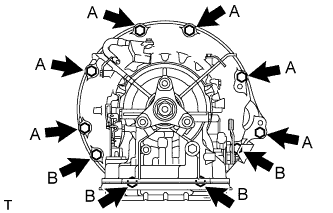
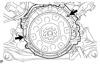
Install the automatic transmission to the engine with the 10 bolts.
- Torque:
- Bolt A
- 71 N*m { 724 kgf*cm, 52 ft.*lbf, for 17 mm bolt }
- Bolt B
- 37 N*m { 377 kgf*cm, 27 ft.*lbf, for 14 mm bolt }
Note
-
Insert dowel pins into the dowel holes securely so that the end face of the automatic transmission assembly fits close against the engine assembly before tightening the bolts.
-
Make sure that the dowel pins are not loose, bent, damaged or scratched and then install the transaxle onto the engine with the contact surfaces of the engine and transaxle flat against each other.
-
-
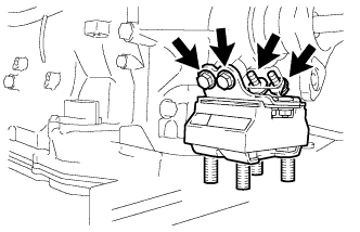
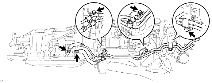
CONNECT WIRE HARNESS AND CONNECTOR
-
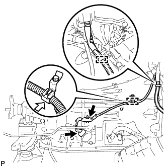
Install the nut and 2 wire harness clamps.
- Torque:
- 10 N*m { 102 kgf*cm, 7 ft.*lbf }
-
Connect the park/neutral position switch connector.
-
Install the 2 bolts and wire harness clamp.
- Torque:
- 10 N*m { 102 kgf*cm, 7 ft.*lbf }
-
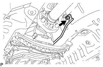
Connect the transmission wire connector.
Tech Tips
Push up the lever until the claw of the transmission wire connector makes a connection sound.
-
-
CONNECT BREATHER PLUG HOSE
-
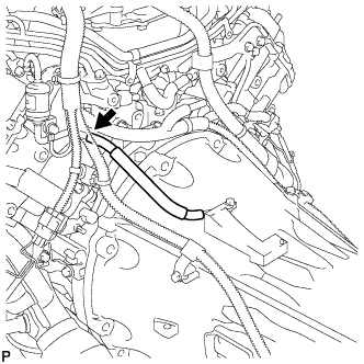
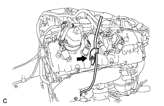
Connect the breather hose to the transmission breather assembly.
Tech Tips
Be sure to insert the breather hose until stopped by the protrusion on the transmission breather assembly.
-
-
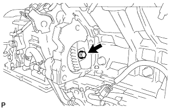
INSTALL TRANSMISSION CONTROL SHAFT LEVER RH
-
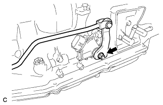
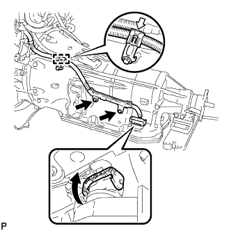
Install the transmission control shaft lever with the nut.
- Torque:
- 16 N*m { 160 kgf*cm, 12 ft.*lbf }
-
-
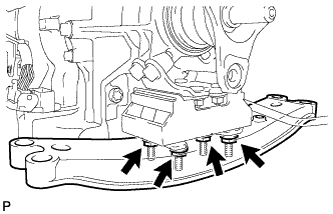
INSTALL REAR ENGINE MOUNTING INSULATOR ASSEMBLY
-
Install the rear engine mounting insulator with the 4 bolts.
- Torque:
- 30 N*m { 306 kgf*cm, 22 ft.*lbf }
-
-
INSTALL REAR ENGINE MOUNTING MEMBER
-
Install the engine rear mounting member to the automatic transmission assembly with the 4 nuts.
- Torque:
- 13 N*m { 133 kgf*cm, 10 ft.*lbf }
-
-
INSTALL DRIVE PLATE AND TORQUE CONVERTER CLUTCH SETTING BOLT
-
Install the 6 torque converter clutch setting bolts.
- Torque:
- 48 N*m { 489 kgf*cm, 35 ft.*lbf }
Tech Tips
First install the black colored bolt and then the remaining 5 bolts.
-
-
CONNECT OIL COOLER TUBE SUB-ASSEMBLY
-
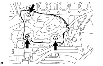
Install the oil cooler tube bracket with the 3 bolts.
- Torque:
- 14 N*m { 140 kgf*cm, 10 ft.*lbf }
-
Install the 2 oil cooler tubes with the 2 clips.
-
-
INSTALL NO. 1 EXHAUST PIPE SUPPORT BRACKET SUB-ASSEMBLY
-
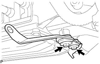
Install the No. 1 exhaust pipe support bracket with the 2 bolts.
- Torque:
- 43 N*m { 439 kgf*cm, 32 ft.*lbf }
-
-
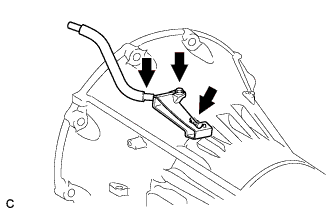
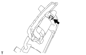
INSTALL STARTER ASSEMBLY
-
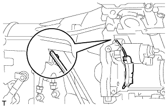
Install the flywheel housing side cover.
-
Install the terminal lower cover with the nut.
- Torque:
- 10 N*m { 102 kgf*cm, 7 ft.*lbf }
-
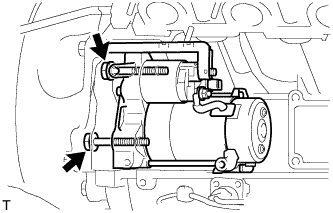
Install the starter assembly with the 2 bolts.
- Torque:
- 37 N*m { 377 kgf*cm, 27 ft.*lbf }
Note
Make sure that the flywheel housing side cover is as shown in the illustration.
-
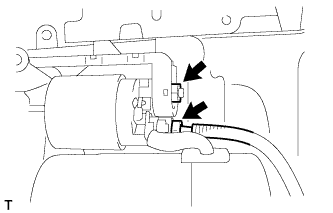
Install the wire harness with the nut.
- Torque:
- 9.8 N*m { 100 kgf*cm, 87 in.*lbf }
-
Connect the starter connector.
-
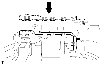
Install the terminal upper cover with the 11 claws.
-
-
INSTALL NO. 3 EXHAUST MANIFOLD HEAT INSULATOR
-
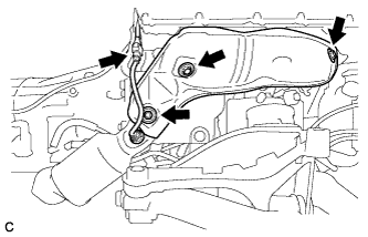
Install the No. 3 exhaust manifold heat insulator with the 3 bolts.
- Torque:
- 10 N*m { 102 kgf*cm, 7 ft.*lbf }
-
-
INSTALL EXHAUST MANIFOLD SUB-ASSEMBLY RH
-
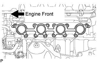
Install a new gasket.
-
Install the exhaust manifold sub-assembly RH, and install 8 new nuts in the order shown in the illustration.
- Torque:
- 21 N*m { 214 kgf*cm, 16 ft.*lbf }
-
-
INSTALL NO. 1 EXHAUST MANIFOLD HEAT INSULATOR
-
Install the No. 1 exhaust manifold heat insulator with the 3 bolts.
- Torque:
- 10 N*m { 102 kgf*cm, 7 ft.*lbf }
-
Connect the air fuel ratio sensor connector.
-
-
INSTALL ENGINE OIL LEVEL DIPSTICK GUIDE
-
Apply engine oil to a new O-ring, and install it to the oil level dipstick guide sub-assembly.
-
Install the oil level dipstick guide sub-assembly with the bolt.
- Torque:
- 10 N*m { 102 kgf*cm, 7 ft.*lbf }
-
-
INSTALL ENGINE OIL LEVEL DIPSTICK
-
Install the oil level dipstick sub-assembly.
-
-
INSTALL ENGINE AND TRANSMISSION
-
ADD AUTOMATIC TRANSMISSION FLUID
-
Add the automatic transmission fluid Click here.
-
-
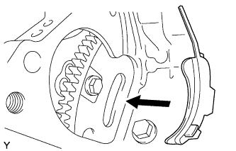
ADJUST SHIFT LEVER POSITION
-
Remove the nut and disconnect the shifting rod.
-
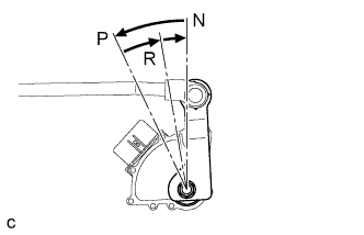
Turn the control shaft lever of the park/neutral position switch counterclockwise until it stops, and turn it clockwise 2 notches to set it to N.
-
Move the shift lever to N and tighten the nut while lightly pushing the lever toward R.
- Torque:
- 13 N*m { 130 kgf*cm, 9 ft.*lbf }
Note
Do not push the shift lever too hard.
-
Check that the shift lever moves smoothly and the shift lever and gear operate correctly Click here.
-
-
INSPECT SHIFT LEVER POSITION
-
When shifting from P to R with the engine switch on (IG) and the brake pedal depressed, make sure that the shift lever moves smoothly and moves correctly into the position.
-
Check that the shift lever does not stop when moving the shift lever from R to P, and check that the shift lever does not stick when moving the shift lever from D to M.
-
Start the engine and make sure that the vehicle moves forward when shifting from N to D and moves rearward when shifting to R.
If an operation cannot be done as specified, inspect the park/neutral position switch assembly and check the shift lever assembly installation condition.
-
-
CHECK AUTOMATIC TRANSMISSION SYSTEM PRECAUTION
-
After replacing the automatic transmission assembly, certain procedures are necessary Click here.
-