OIL PUMP DISASSEMBLY

-
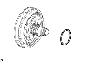
REMOVE OIL PUMP O-RING
-
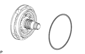
Remove the O-ring from the oil pump.
-
-
SECURE OIL PUMP ASSEMBLY
-
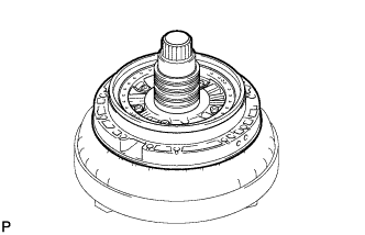
Place the oil pump body on the torque converter clutch.
-
-
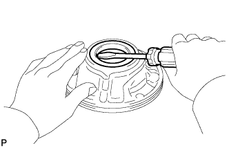
REMOVE CLUTCH DRUM OIL SEAL RING
-
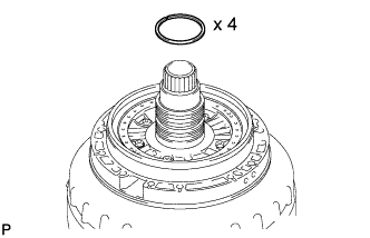
Remove the 4 oil seal rings.
-
-
REMOVE STATOR SHAFT PISTON
-
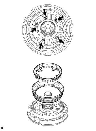
Using a T30 ''TORX'' wrench, remove the 5 bolts, stator shaft spring sub-assembly and stator shaft piston.
-
Remove the 2 O-rings from the stator shaft piston.
-
-
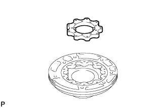
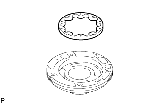
REMOVE STATOR SHAFT CLUTCH DRUM THRUST WASHER
-
Remove the stator shaft clutch drum thrust washer.
-
-
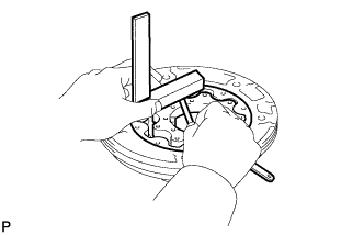
INSPECT STATOR SHAFT SPRING SUB-ASSEMBLY
-
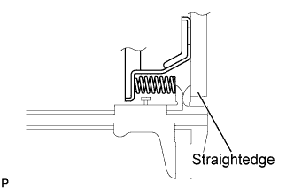
Using a vernier caliper and straightedge, measure the distance between the spring end and the straightedge.
Standard thickness 6.52 mm (0.257 in.)
-
-
REMOVE STATOR SHAFT ASSEMBLY
-
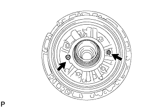
Remove the 2 bolts and stator shaft from the oil pump body.
-
-
REMOVE FRONT OIL PUMP BODY O-RING
-
Remove the oil pump body from the torque converter clutch.
-
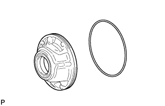
Remove the O-ring from the oil pump body.
-
-
INSPECT STATOR SHAFT ASSEMBLY
-
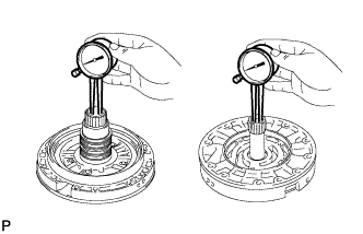
Using a caliper gauge, measure the inside diameter of the stator shaft bush.
Maximum inside diameter Front side 25.925 mm (1.02 in.) Rear side 35.251 mm (1.39 in.) If the inside diameter is greater than the maximum, replace the stator shaft assembly.
-
-
INSPECT FRONT OIL PUMP BODY SUB-ASSEMBLY
-
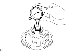
Using a caliper gauge, measure the inside diameter of the oil pump body bush.
Maximum inside diameter 45.078 mm (1.77 in.) If the inside diameter is greater than the maximum, replace the oil pump body sub-assembly.
-
-
INSPECT CLEARANCE OF OIL PUMP ASSEMBLY
-
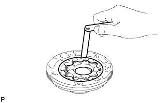
Push the driven gear to one side of the pump body.
-
Using a feeler gauge, measure the clearance between the driven gear and pump body.
Standard body clearance 0.10 to 0.17 mm (0.00394 to 0.00669 in.) If the clearance is not as specified, replace the drive gear, driven gear and pump body.
-
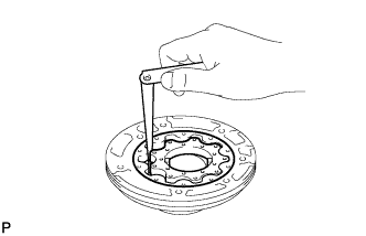
Using a feeler gauge, measure the clearance between the driven gear teeth and drive gear teeth.
Standard tip clearance 0.07 to 0.15 mm (0.00276 to 0.00591 in.) If the tip clearance is not as specified, replace the drive gear, driven gear and pump body.
-
Using a steel straightedge and feeler gauge, measure the clearance between both gears and the straightedge.
Standard side clearance 0.03 to 0.05 mm (0.00118 to 0.00197 in.) If the side clearance is not as specified, replace the drive gear, driven gear and pump body.
Tech Tips
There are 7 different thicknesses for the drive and driven gears.
Standard Drive and Driven Gear Thickness Mark Thickness 0 11.636 to 11.642 mm (0.45811 to 0.45835 in.) 1 11.643 to 11.649 mm (0.45838 to 0.45862 in.) 2 11.650 to 11.656 mm (0.45866 to 0.45890 in.) 3 11.657 to 11.663 mm (0.45894 to 0.45917 in.) 4 11.664 to 11.670 mm (0.45921 to 0.45945 in.) 5 11.671 to 11.677 mm (0.45949 to 0.45972 in.) 6 11.678 to 11.684 mm (0.45976 to 0.46000 in.)
-
-
REMOVE FRONT OIL PUMP DRIVE GEAR
-
Remove the drive gear from the oil pump body.
-
-
REMOVE FRONT OIL PUMP DRIVEN GEAR
-
Remove the driven gear from the oil pump body.
-
-
REMOVE FRONT OIL PUMP OIL SEAL
-
Using a screwdriver, pry out the oil seal.
Note
Do not damage the bushing or oil pump body.
-