PARK / NEUTRAL POSITION SWITCH REMOVAL

-
REMOVE NO. 2 FLOOR UNDER COVER
-
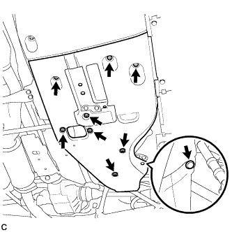
Remove the 6 clips, 3 grommets, and No. 2 floor under cover.
-
-
REMOVE NO. 1 FLOOR UNDER COVER
-
Remove the 5 clips, 3 grommets, and No. 1 floor under cover.
-
-
REMOVE TAIL EXHAUST PIPE ASSEMBLY
-
Remove the 2 bolts and 2 compression springs.
-
Remove the tail exhaust pipe assembly from the 6 exhaust pipe supports.
-
Remove the gasket from the front exhaust pipe assembly.
-
-
REMOVE REAR NO. 1 FLOOR PANEL BRACE
-
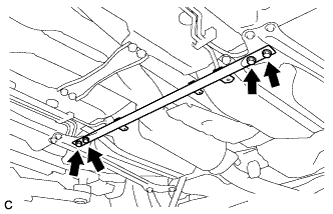
Remove the 4 bolts and rear No. 1 floor panel brace.
-
-
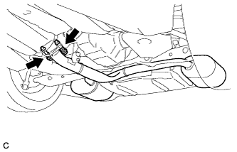
REMOVE FRONT CENTER FLOOR BRACE
-
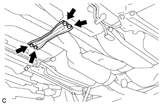
Remove the 4 bolts and front center floor brace.
-
-
DISCONNECT HEATED OXYGEN SENSOR
-
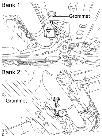
Remove the grommets of the heated oxygen sensors.
-
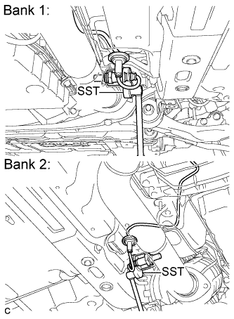
Using SST, loosen the heated oxygen sensors, and disconnect the sensors by hand.
- SST
- 09224-00010
-
-
REMOVE FRONT EXHAUST PIPE ASSEMBLY
-
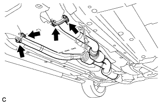
Remove the 4 bolts, 4 nuts and front exhaust pipe assembly.
-
Remove the 2 gaskets from the exhaust manifold RH and exhaust manifold LH.
-
-
REMOVE FRONT NO. 1 FLOOR HEAT INSULATOR
-
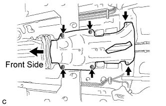
Remove the 4 nuts, 2 bolts and front No. 1 floor heat insulator.
-
-
REMOVE OUTSIDE AIR GUIDE PLATE RH
-
Remove the 4 nuts and outside air guide plate RH.
-
-
REMOVE PROPELLER SHAFT WITH CENTER BEARING ASSEMBLY
-
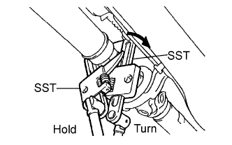
Using SST, loosen the adjusting nut until it can be turned by hand.
- SST
- 09922-10010
Tech Tips
Use 2 of the same SST.
-
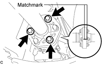
Put matchmarks on the transmission companion flange, flexible coupling and intermediate shaft.
-
Remove the 3 bolts, 3 washers and 3 nuts.
Note
Do not separate the propeller shaft and flexible coupling.
-
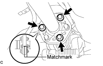
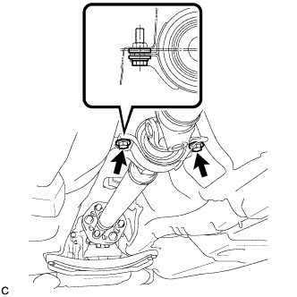
Put matchmarks on the differential companion flange, flexible coupling and propeller shaft.
-
Remove the 3 bolts, 3 washers and 3 nuts.
Note
Do not separate the propeller shaft and flexible coupling.
-
Remove the 2 center support bearing set bolts and 2 center support bearing washers.
Tech Tips
Some vehicles are not equipped with center support bearing washers.
-
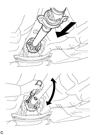
Push the propeller shaft with center bearing assembly straight ahead to compress and pull out the propeller shaft with center bearing assembly from the differential centering pin.
Note
Press the propeller shaft straight ahead to keep the transmission and intermediate shaft aligned straight.
Tech Tips
If it is difficult to separate the flange from the flexible coupling, pry it using a screwdriver.
-
Pull the propeller shaft outward from the rear of the vehicle.
Note
Do not separate the intermediate shaft and propeller shaft.
-
-
REMOVE NO. 2 ENGINE UNDER COVER
-
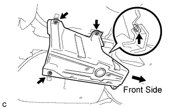
REMOVE ENGINE UNDER COVER AIR GUIDE BRACKET
-
Remove the 2 bolts and engine under cover air guide bracket.
-
-
DISCONNECT FLOOR SHIFT GEAR SHIFTING ROD SUB-ASSEMBLY
-
Remove the nut and disconnect the floor shift gear shifting rod.
-
-
SUPPORT AUTOMATIC TRANSMISSION ASSEMBLY
-
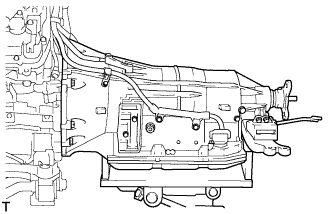
Support the automatic transmission assembly with a transmission jack.
-
-
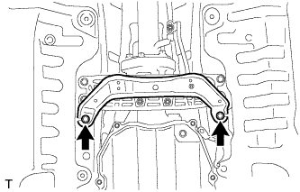
DISCONNECT REAR ENGINE MOUNTING MEMBER
-
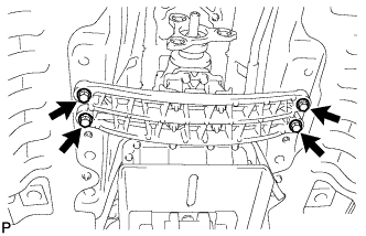
Remove the 4 bolts, and disconnect the engine rear mounting member from the body.
-
-
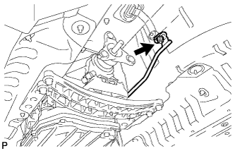
REMOVE PARK/NEUTRAL POSITION SWITCH ASSEMBLY
-
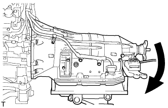
Tilt down the automatic transmission assembly.
-
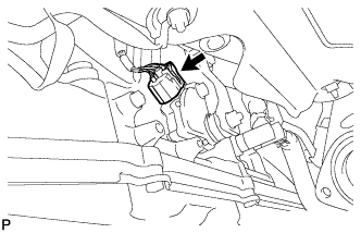
Disconnect the switch connector.
-
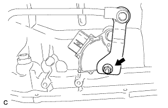
Remove the nut, spring washer and transmission control shaft lever with shifting rod.
-
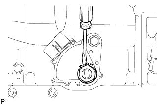
Using a screwdriver, pry off the lock washer.
-
Remove the lock nut and lock washer.
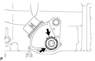
-
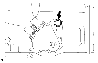
Remove the bolt and switch.
Tech Tips
Make sure that the manual valve lever shaft has not been rotated prior to installing the park/neutral position switch assembly as the detent spring may become detached from the manual valve lever shaft.
-