SPEED SENSOR INSTALLATION

-
INSTALL SPEED SENSOR SP2
-
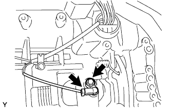
Install the speed sensor to the transmission case with the bolt.
- Torque:
- 5.4 N*m { 55 kgf*cm, 48 in.*lbf }
-
Connect the sensor connector.
-
-
INSTALL SPEED SENSOR NC3
-
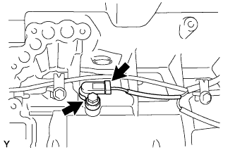
Install the speed sensor to the transmission case with the bolt.
- Torque:
- 5.4 N*m { 55 kgf*cm, 48 in.*lbf }
-
Connect the sensor connector.
-
-
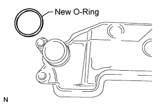
INSTALL SPEED SENSOR NT
-
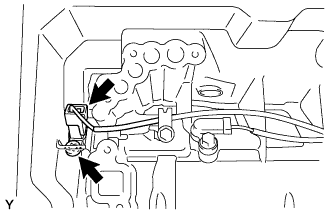
Coat a new O-ring with ATF and install it to the speed sensor.
-
Using a T30 ''TORX'' wench, install the speed sensor with the bolt.
- Torque:
- 6.8 N*m { 69 kgf*cm, 60 in.*lbf }
-
Connect the sensor connector.
-
-
INSTALL TRANSMISSION VALVE BODY ASSEMBLY
-
Install the spring and check ball body.
-
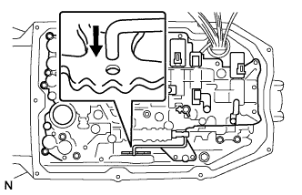
Align the groove of the manual valve with the lever pin.
-
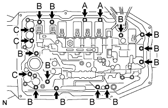
Install the 17 bolts.
- Torque:
- 11 N*m { 112 kgf*cm, 8 ft.*lbf }
Tech Tips
Each bolt length is indicated below.
Bolt length 21 mm (0.827 in.) for bolt A 31 mm (1.22 in.) for bolt B 64 mm (2.52 in.) for bolt C -
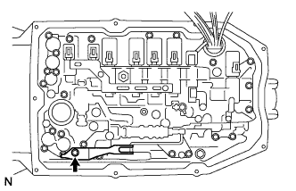
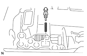
Install the detent spring and detent spring cover with the bolt.
Note
Make sure to install the detent spring so that its roller is perpendicularly aligned to the center of the manual valve lever.
- Torque:
- 10 N*m { 102 kgf*cm, 7 ft.*lbf }
-
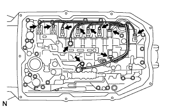
Connect the 9 connectors to the solenoid valves.
-
Connect the oil pressure switch connector.
-
Coat a new O-ring with ATF and install to the ATF temperature sensor.
-
Install the ATF temperature sensor and lock plate with the bolt.
- Torque:
- 10 N*m { 102 kgf*cm, 7 ft.*lbf }
-
-
INSTALL VALVE BODY OIL STRAINER ASSEMBLY
-
Coat a new O-ring with ATF and install it to the oil strainer.
Note
Ensure that the O-ring is not twisted or pinched.
-
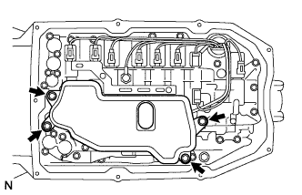
Install the oil strainer to the valve body with the 4 bolts.
- Torque:
- 11 N*m { 112 kgf*cm, 8 ft.*lbf }
-
-
INSTALL AUTOMATIC TRANSMISSION OIL PAN SUB-ASSEMBLY
-
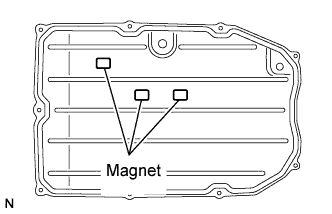
Install the 3 magnets to the oil pan.
-
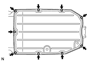
Install a new gasket and the oil pan to the transmission case with the 9 bolts.
- Torque:
- 7.4 N*m { 75 kgf*cm, 65 in.*lbf }
Note
-
-
Make sure that there is no oil or foreign matter on the gasket seal surface and oil pan contact surface.
-
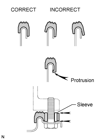
Install the gasket so that there is no slack in the gasket, and that the entire seal surface is level.
-
Make sure that the 9 gasket drop prevention protrusions are set on the oil pan.
-
When tightening the oil pan, make sure that the gasket is not pinched between the gasket tightening area sleeve and the transmission seal surface.
-
-
INSTALL NO. 1 EXHAUST PIPE SUPPORT BRACKET SUB-ASSEMBLY
-
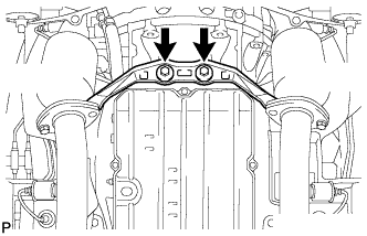
Install the No. 1 exhaust pipe support bracket with the 2 bolts.
- Torque:
- 43 N*m { 439 kgf*cm, 32 ft.*lbf }
-
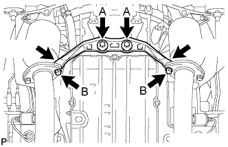
Install the No. 1 exhaust pipe support bracket with with 2 new bolts and 2 new nuts.
- Torque:
- 39 N*m { 398 kgf*cm, 29 ft.*lbf }
-
-
ADD AUTOMATIC TRANSMISSION FLUID
-
Add automatic transmission fluid Click here.
-
-
INSTALL NO. 2 ENGINE UNDER COVER