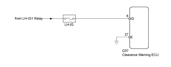
LEXUS PARKING ASSIST-SENSOR SYSTEM Clearance Warning ECU Power Source Circuit
DESCRIPTION
This circuit provides power to operate the clearance warning ECU.
WIRING DIAGRAM
INSPECTION PROCEDURE
PROCEDURE
-
INSPECT FUSE (LH-IG)
-
Remove the LH-IG fuse from the cowl side junction block LH.
-
Measure the resistance of the LH-IG fuse.
Standard Resistance Tester Item Condition Specified Condition LH-IG fuse Always Below 1 Ω
NG 
REPLACE FUSE (LH-IG)
OK 
-
-
CHECK HARNESS AND CONNECTOR (CLEARANCE WARNING ECU - BATTERY)
-
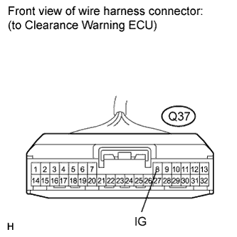
Disconnect the clearance warning ECU connector.
-
Measure the voltage according to the value(s) on the table below.
Standard Voltage Tester Connection Condition Specified Condition Q37-8 (IG) - Body ground Engine switch on (IG) 11 to 14 V
NG
REPAIR OR REPLACE HARNESS OR CONNECTOR
OK
-
-
CHECK HARNESS AND CONNECTOR (CLEARANCE WARNING ECU - BODY GROUND)
-
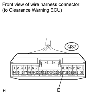
Measure the resistance according to the value(s) in the table below.
Standard Resistance Tester Connection Condition Specified Condition Q37-27 (E) - Body ground Always Below 1 Ω
NG
REPAIR OR REPLACE HARNESS OR CONNECTOR
OK 
PROCEED TO NEXT CIRCUIT INSPECTION SHOWN IN PROBLEM SYMPTOMS TABLE Click here
-