LEXUS PARKING ASSIST-SENSOR SYSTEM No. 1 Clearance Warning Buzzer Circuit
DESCRIPTION
The clearance warning ECU receives the ultrasonic sensor signal to sound the clearance warning buzzer.
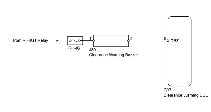
WIRING DIAGRAM
INSPECTION PROCEDURE
PROCEDURE
-
PERFORM ACTIVE TEST USING INTELLIGENT TESTER
-
Connect the intelligent tester to the DLC3.
-
Turn the engine switch on (IG).
-
Turn the intelligent tester on.
-
Turn the clearance sonar main switch ON.
-
Select the Active Test, use the intelligent tester to generate a control command, and then check that the buzzer operates.
Clearance Sonar Tester Display Test Part Control Range Diagnostic Note Rear Buzzer Rear buzzer (Clearance warning buzzer) STOP or OPERATE - OK The clearance warning buzzer sounds.
NG 
INSPECT FUSE (RH-IG) Click here
OK 
PROCEED TO NEXT CIRCUIT INSPECTION SHOWN IN PROBLEM SYMPTOMS TABLE Click here
-
-
INSPECT FUSE (RH-IG)
-
Remove the RH-IG fuse from the cowl side center junction block RH
-
Measure the resistance of the RH-IG fuse.
Standard Resistance Tester Item Condition Specified Condition RH-IG fuse Always Below 1 Ω
NG 
REPLACE FUSE (RH-IG)
OK 
-
-
CHECK HARNESS AND CONNECTOR (CLEARANCE WARNING BUZZER - BATTERY)
-
Disconnect the clearance warning buzzer connector.
-
Measure the voltage according to the value(s) in the table below.
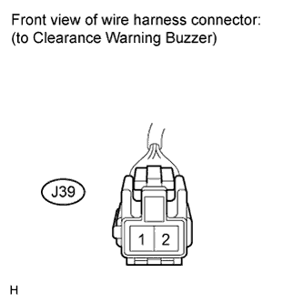
Standard Voltage Tester Connection Condition Specified Condition J39-1 - Body ground Engine switch on (IG) 11 to 14 V
NG
REPAIR OR REPLACE HARNESS OR CONNECTOR
OK
-
-
CHECK HARNESS AND CONNECTOR (CLEARANCE WARNING ECU - CLEARANCE WARNING BUZZER)
-
Disconnect the clearance warning ECU connector.
-
Measure the resistance according to the value(s) in the table below.
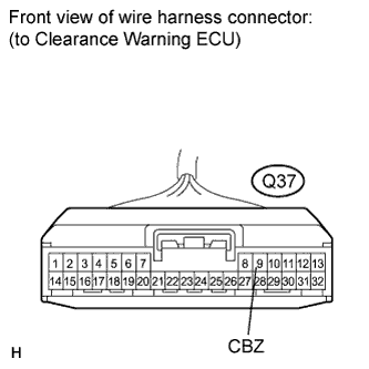
Standard Resistance Tester Connection Condition Specified Condition Q37-9 (CBZ) - J39-2 Always Below 1 Ω Q37-9 (CBZ) - Body ground Always 10 kΩ or higher
NG
REPAIR OR REPLACE HARNESS OR CONNECTOR
OK
-
-
INSPECT CLEARANCE WARNING BUZZER
-
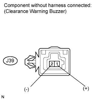
Apply battery voltage and check operation of the clearance warning buzzer, as shown in the table.
OK Measurement Condition Specified Condition Battery positive (+) → J39-1
Battery negative (-) → J39-2
Operating sound occurs Tech Tips
The clearance warning buzzer does not sound without battery voltage applied because the buzzer is a separately-excited type.
NG
REPLACE CLEARANCE WARNING BUZZER Click here
OK
REPLACE CLEARANCE WARNING ECU Click here
-