LEXUS PARKING ASSIST-SENSOR SYSTEM, Diagnostic DTC:B2232

| DTC Code | DTC Name |
|---|---|
| B2232 | Front Left Sensor Malfunction |
DESCRIPTION
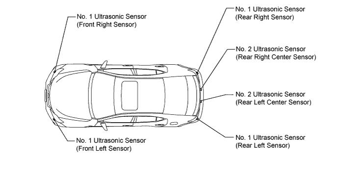
The No. 1 ultrasonic sensor (front left sensor) is installed on the front bumper.
The clearance warning ECU detects obstacles based on signals received from the front left sensor. If the front left sensor's circuit has an open, short or other malfunction, it will not function normally.
| DTC No. | DTC Detection Condition | Trouble Area |
|---|---|---|
| B2232 | Malfunction of No. 1 ultrasonic sensor (Front left sensor) |
|
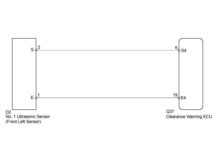
WIRING DIAGRAM
INSPECTION PROCEDURE
PROCEDURE
-
INSPECT NO. 1 ULTRASONIC SENSOR
-
Remove the No. 1 ultrasonic sensor.
-
Disconnect the No. 1 ultrasonic sensor connector.
-
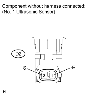
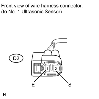
Measure the resistance according to the value(s) in the table below.
Standard Resistance Tester Connection Condition Specified Condition D2-2 (S) - D2-1 (E) Always 600 to 1200 kΩ Note
Set the tester to the 100 kΩ range before performing the measurement.
NG 
REPLACE NO. 1 ULTRASONIC SENSOR (FRONT LEFT SENSOR) Click here
OK 
-
-
CHECK HARNESS AND CONNECTOR (CLEARANCE WARNING ECU - NO. 1 ULTRASONIC SENSOR)
-
Disconnect the clearance warning ECU connector.
-
Measure the resistance according to the value(s) in the table below.
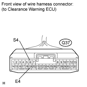
Standard Resistance Tester Connection Condition Specified Condition Q37-6 (S4) - D2-2 (S) Always Below 1 Ω Q37-19 (E4) - D2-1 (E) Always Below 1 Ω Q37-6 (S4) - Body ground Always 10 kΩ or higher Q37-19 (E4) - Body ground Always 10 kΩ or higher Result Result Proceed to NG A OK (When troubleshooting according to the Problem Symptoms Table) B OK (When troubleshooting according to the DTC) C
B
PROCEED TO NEXT CIRCUIT INSPECTION SHOWN IN PROBLEM SYMPTOMS TABLE Click here
C
REPLACE CLEARANCE WARNING ECU Click here
A 
REPAIR OR REPLACE HARNESS OR CONNECTOR
-