AUTOMATIC TRANSMISSION SYSTEM, Diagnostic DTC:P2716

| DTC Code | DTC Name |
|---|---|
| P2716 | Pressure Control Solenoid "D" Electrical (Shift Solenoid Valve SLT) |
DESCRIPTION
Refer to DTC P2714 Click here.
| DTC Code | DTC Detection Condition
|
Trouble Area |
|---|---|---|
| P2716 |
|
|
MONITOR DESCRIPTION
When an open or short in the shift solenoid valve SLT circuit is detected, the TCM interprets this as a fault. The TCM will turn on the MIL and store the DTC.
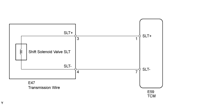
WIRING DIAGRAM
INSPECTION PROCEDURE
PROCEDURE
-
CHECK HARNESS AND TRANSMISSION WIRE (TRANSMISSION WIRE - TCM, TRANSMISSION WIRE (SHIFT SOLENOID VALVE SLT))
-
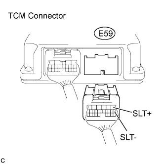
Disconnect the TCM connector.
-
Measure the resistance according to the value(s) in the table below.
Standard Resistance Tester Connection Condition Specified Condition E59-1 (SLT+) - E59-7 (SLT-) Always 5.0 to 5.6 Ω E59-1 (SLT+) or E59-7 (SLT-) - Body ground Always 10 kΩ or higher
NG 
CHECK HARNESS AND CONNECTOR (TRANSMISSION WIRE - TCM) Click here
OK 
-
-
REPLACE TCM
-
Replace the TCM Click here.
NEXT 
PERFORM A/T CODE REGISTRATION Click here
-
-
CHECK HARNESS AND CONNECTOR (TRANSMISSION WIRE - TCM)
-
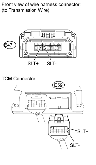
Disconnect the transmission wire connector.
-
Disconnect the TCM connector.
-
Measure the resistance according to the value(s) in the table below.
Standard Resistance Tester Connection Condition Specified Condition E47-3 (SLT+) - E59-1 (SLT+) Always Below 1 Ω E47-4 (SLT-) - E59-7 (SLT-) Always Below 1 Ω E47-3 (SLT+) or E59-1 (SLT+) - Body ground Always 10 kΩ or higher E47-4 (SLT-) or E59-7 (SLT-) - Body ground Always 10 kΩ or higher
NG 
REPAIR OR REPLACE HARNESS OR CONNECTOR
OK
-
-
INSPECT SHIFT SOLENOID VALVE SLT
-
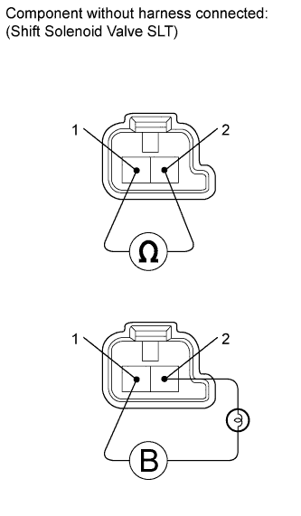
Remove the shift solenoid valve SLT Click here.
-
Measure the resistance according to the value(s) in the table below.
Standard Resistance Tester Connection Condition Specified Condition Terminal 1 of the shift solenoid valve SLT - terminal 2 20°C (68°F) 5.0 to 5.6 Ω -
Connect a batterya positive (+) lead with a 21 W bulb to terminal 2 and a negative (-) lead to terminal 1 of the solenoid valve connector. Then check that the valve moves and makes an operating sound.
OK Valve moves and makes an operating sound.
NG
REPLACE SHIFT SOLENOID VALVE SLT Click here
OK
REPAIR OR REPLACE TRANSMISSION WIRE Click here
-