AUTOMATIC TRANSMISSION SYSTEM, Diagnostic DTC:P2714

| DTC Code | DTC Name |
|---|---|
| P2714 | Pressure Control Solenoid "D" Performance (Shift Solenoid Valve SLT) |
SYSTEM DESCRIPTION
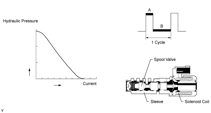
Based on signals from the accelerator position sensor and speed sensors (NC3, SP2 and NT), the TCM controls the solenoid valve (SLT) using a predetermined duty ratio*. As a result, the line pressure is adjusted to a pressure that is appropriate for the throttle angle and engine output. Based on rotation speed from the transmission speed sensors (NT, NC3 and SP2), the TCM calculates the heat level of the friction material, and detects clutch slippage, etc.
Tech Tips
*: The duty ratio is the ratio of the current ON time (A) to the total of the current ON and OFF time (A + B).
Duty Ratio (%) = A / (A + B) x 100
| DTC Code | DTC Detection Condition
|
Trouble Area |
|---|---|---|
| P2714 |
|
|
MONITOR DESCRIPTION
The TCM calculates the amount of heat absorbed by the friction material based on the difference in revolution speed (clutch slippage) between the turbine and output shaft. The TCM illuminates the MIL and outputs this DTC when the amount of heat absorption exceeds the specified value.
When the shift solenoid valve SLT remains ON, oil pressure goes down and clutch engagement force decreases.
Note
If driving continues under these conditions, clutches will burn out and the vehicle will no longer be drivable.
INSPECTION PROCEDURE
PROCEDURE
-
CHECK DTC OUTPUT (IN ADDITION TO DTC P0746, P0771, P0776, P0796, P2714, P2808 AND P2817)
-
Connect the intelligent tester to the DLC3.
-
Turn the engine switch on (IG).
-
Turn the intelligent tester on.
-
Enter the following menus: Powertrain / ECT / Trouble Codes.
-
Read the DTCs using the intelligent tester.
Result Display (DTC Output) Proceed to P2714 and one or more of the following DTCs are output: P0746, P0771, P0776, P0796, P2808, P2817 A Only P2714 is output B P0746, P0771, P0776, P0796, P2714, P2808 or P2817 and other DTCs are output C Tech Tips
If any other codes besides P0746, P0771, P0776, P0796, P2714, P2808 and P2817 are output, perform troubleshooting for those DTCs first.
B 
INSPECT SHIFT SOLENOID VALVE SLT Click here
C 
GO TO DTC CHART Click here
A 
-
-
CHECK FOR OUTPUT DTCS OTHER THAN P2714
-
Check if DTCs other than P2714 are output.
Result Display (DTC Output) Proceed to P2714 and P0746 are output A
-
P2714, P0771 and P0776 are output
-
P2714 and P0776 are output
B
-
P2714, P0771 and P0796 are output
-
P2714 and P0796 are output
-
P2714, P0796 and P2808 are output
C P2714 and P2808 are output D P2714 and P2817 are output E -
B
GO TO DTC P0776 FLOWCHART Click here
C
GO TO DTC P0796 FLOWCHART Click here
D
GO TO DTC P2808 FLOWCHART Click here
E
GO TO DTC P2817 FLOWCHART Click here
A 
GO TO DTC P0746 FLOWCHART Click here
-
-
INSPECT SHIFT SOLENOID VALVE SLT
-
Remove the shift solenoid valve SLT Click here.
-
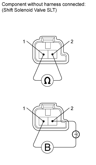
Measure the resistance according to the value(s) in the table below.
Standard Resistance Tester Connection Condition Specified Condition Terminal 1 of the shift solenoid valve SLT - terminal 2 20°C (68°F) 5.0 to 5.6 Ω -
Connect a battery positive (+) lead with a 21 W bulb to terminal 2 and a negative (-) lead to terminal 1 of the solenoid valve connector. Then check that the valve moves and makes an operating sound.
OK Valve moves and makes an operating sound.
NG
REPLACE SHIFT SOLENOID VALVE SLT Click here
OK
-
-
INSPECT TRANSMISSION VALVE BODY ASSEMBLY
-
Check the transmission valve body assembly Click here.
OK There are no foreign objects on any valve.
NG
REPAIR OR REPLACE TRANSMISSION VALVE BODY ASSEMBLY Click here
OK
REPAIR OR REPLACE AUTOMATIC TRANSMISSION ASSEMBLY Click here
-