AUTOMATIC TRANSMISSION SYSTEM TCM Power Source Circuit
DESCRIPTION
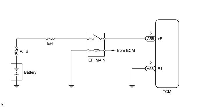
When the engine switch is turned on (IG), voltage from the ECM MREL terminal is applied to the EFI MAIN relay. This causes the contacts of the EFI MAIN relay to close, which supplies power to terminal +B of the TCM.
WIRING DIAGRAM
INSPECTION PROCEDURE
PROCEDURE
-
CHECK HARNESS AND CONNECTOR (TCM - BODY GROUND)
-
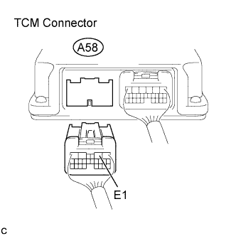
Disconnect the TCM connectors.
-
Turn the engine switch off.
-
Measure the resistance according to the value(s) in the table below.
Standard Resistance Tester Connection Condition Specified Condition A58-2 (E1) - Body ground Always Below 1 Ω
NG 
REPAIR OR REPLACE HARNESS OR CONNECTOR
OK 
-
-
CHECK HARNESS AND CONNECTOR (BATTERY - TCM)
-
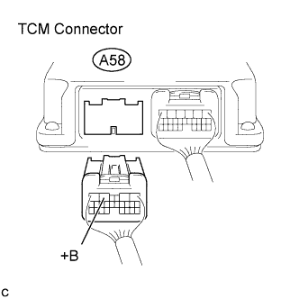
Disconnect the TCM connectors.
-
Turn the engine switch on (IG).
-
Measure the voltage according to the value(s) in the table below.
Standard Voltage Tester Connection Switch Condition Specified Condition A58-5 (+B) - Body ground Engine switch on (IG) 11 to 14 V
NG
REPAIR OR REPLACE HARNESS OR CONNECTOR
OK 
GO TO ECM POWER SOURCE CIRCUIT (ENGINE CONTROL SYSTEM / SFI SYSTEM) Click here
-