AUTOMATIC TRANSMISSION SYSTEM Pattern Select Switch Sport Mode Circuit
DESCRIPTION
The pattern select switch makes it possible to select SPORT modes.
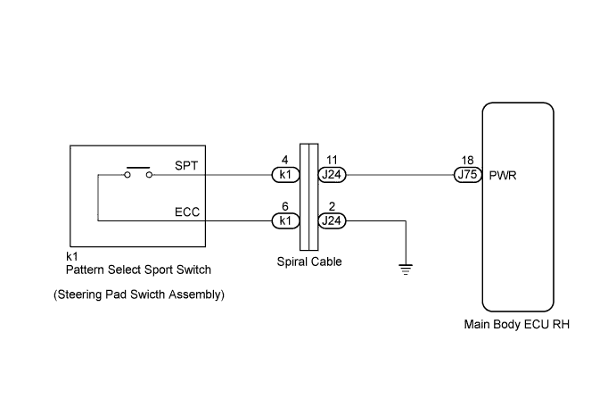
The cowl side junction block ECU (main body ECU RH) receives pattern select switch information, and sends it through the multiplex communication system and CAN system to each ECU.
The SPORT signal changes control for the engine, automatic transmission, VDIM and electric power steering in an integrated manner.
When SPORT mode is selected, the SPORT indicator illuminates, VDIM SPORT mode is entered, and the electric power steering, automatic transmission control and engine control all change to SPORT mode.
WIRING DIAGRAM
Tech Tips
-
Pattern Select SPORT Switch
When the SPORT switch is pushed, the switch contact is made and the SPORT mode is selected.
To cancel the SPORT mode, push the SPORT switch once again.
The SPORT mode is automatically cancelled when the engine switch is turned off.
INSPECTION PROCEDURE
PROCEDURE
-
INSPECT STEERING PAD SWITCH ASSEMBLY (PATTERN SELECT SPORT SWITCH)
-
Remove the steering pad Click here.
-
Disconnect the connector of steering pad switch.
-
Measure the resistance according to the value(s) in the table below.
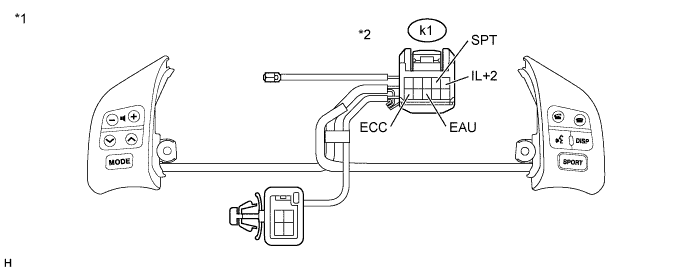
Text in Illustration *1 Steering Pad Switch Assembly *2 Front view of wire harness connector
(to Pattern Select Sport Switch)
Standard Resistance Tester Connection Condition Specified Condition k1-6 (ECC) - k1-4 (SPT) Press continuously pattern select switch
(SPORT)
Below 2.5 Ω Release pattern select switch
(SPORT)
10 kΩ or higher -
Apply battery voltage between the terminals of the switch, and check the illumination condition of the pattern select sport switch.
Tech Tips
-
If a positive (+) battery lead and a negative (-) battery lead are incorrectly connected, the pattern select sport switch indicator light will not illuminate.
If the voltage is too low, the indicator light will not illuminate.
OK Measurement Condition Specified Condition Battery positive (+) → Terminal 5 (IL+2)
Battery negative (-) → Terminal 8 (EAU)
Illuminates If the result is not as specified, replace the steering pad switch.
-
NG 
REPLACE STEERING PAD SWITCH ASSEMBLY Click here
OK 
-
-
INSPECT SPIRAL CABLE SUB-ASSEMBLY
-
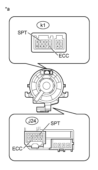
Text in Illustration *a Component without harness connected
(Spiral Cable)
Disconnect the spiral cable connector.
-
Measure the resistance according to the value(s) in the table below.
Standard Resistance Tester Connection Condition Specified Condition k1-4 (SPT) - J24-11 (SPT) Always Below 1 Ω k1-6 (ECC) - J24-2 (ECC) Always Below 1 Ω
NG
REPLACE SPIRAL CABLE SUB-ASSEMBLY Click here
OK
-
-
CHECK HARNESS AND CONNECTOR (SPIRAL CABLE SUB-ASSEMBLY - BODY GROUND)
-
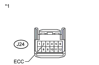
Text in Illustration *1 Front view of wire harness connector
(to Spiral Cable)
Measure the resistance according to the value(s) in the table below.
Standard Resistance Tester Connection Condition Specified Condition J24-2 (ECC) - Body ground Always Below 1 Ω
NG
REPAIR OR REPLACE HARNESS OR CONNECTOR
OK
-
-
CHECK HARNESS AND CONNECTOR (SPIRAL CABLE SUB-ASSEMBLY - MAIN BODY ECU RH)
-
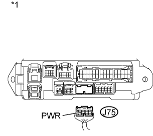
Text in Illustration *1 Rear view of wire harness connector
(to Main Body ECU RH)
Connect the connector of pattern select switch.
-
Disconnect the cowl side junction block (main body ECU RH) connector.
-
Measure the resistance according to the value(s) in the table below.
Standard Resistance Tester Connection Condition Specified Condition J75-18 (PWR) - Body ground Press continuously pattern select switch
(SPORT)
Below 1 Ω Release pattern select switch
(SPORT)
10 kΩ or higher
NG
REPAIR OR REPLACE HARNESS OR CONNECTOR
OK 
PROCEED TO NEXT CIRCUIT INSPECTION SHOWN IN PROBLEM SYMPTOMS TABLE Click here
-