AUTOMATIC TRANSMISSION SYSTEM Pattern Select Switch Snow Mode Circuit
DESCRIPTION
The pattern select switch makes it possible to select Normal or SNOW modes.
The cowl side junction block ECU (main body ECU RH) receives pattern select switch information, and sends it through the multiplex communication system and CAN system to each ECU.
When SNOW is selected, the operation of the throttle motor is moderated to control engine output. This helps to reduce skidding of the drive wheels, and assists with takeoff acceleration, driving straightness and turning stability.
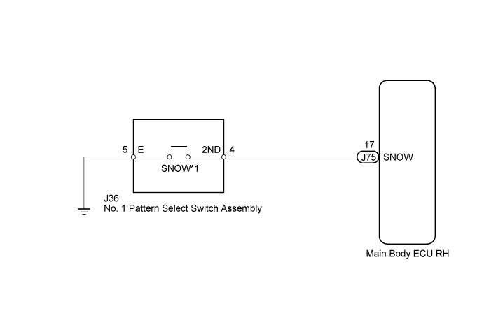
WIRING DIAGRAM
Tech Tips
-
(*1) Pattern Select Switch (SNOW Switch)
When the SNOW switch is pushed, the switch contact is made and the SNOW mode is selected.
To cancel the SNOW mode, push the SNOW switch once again.
The SNOW mode is automatically cancelled when the engine switch is turned off.
INSPECTION PROCEDURE
PROCEDURE
-
CHECK HARNESS AND CONNECTOR (PATTERN SELECT SWITCH ASSEMBLY - BODY GROUND)
-
Disconnect the connector of pattern select switch Click here.
-
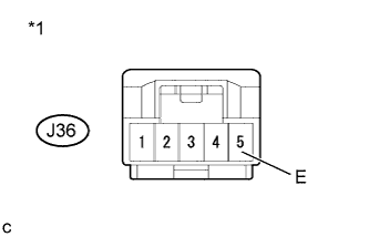
Text in Illustration *1 Front view of wire harness connector
(to Pattern Select Switch)
Measure the resistance according to the value(s) in the table below.
Standard Resistance Tester Connection Condition Specified Condition J36-5 (E) - Body ground Always Below 1 Ω
NG 
REPAIR OR REPLACE HARNESS OR CONNECTOR
OK 
-
-
INSPECT PATTERN SELECT SWITCH ASSEMBLY
-
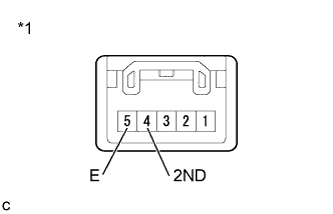
Text in Illustration *1 Component without harness connected
(Pattern Select Switch)
Measure the resistance according to the value(s) in the table below.
Standard Resistance Tester Connection Condition Specified Condition 5 (E) - 4 (2ND) Press continuously pattern select switch
(SNOW)
Below 1 Ω Release pattern select switch
(SNOW)
10 kΩ or higher
NG
REPLACE PATTERN SELECT SWITCH ASSEMBLY Click here
OK
-
-
CHECK HARNESS AND CONNECTOR (PATTERN SELECT SWITCH ASSEMBLY - MAIN BODY ECU)
-
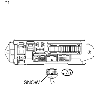
Text in Illustration *1 Rear view of wire harness connector
(to Main Body ECU RH)
Connect the connector of pattern select switch.
-
Disconnect the cowl side junction block (main body ECU RH) connector.
-
Measure the resistance according to the value(s) in the table below.
Standard Resistance Tester Connection Condition Specified Condition J75-17 (SNOW) - Body ground Press continuously pattern select switch
(SNOW)
Below 1 Ω Release pattern select switch
(SNOW)
10 kΩ or higher
NG
REPAIR OR REPLACE HARNESS OR CONNECTOR
OK 
PROCEED TO NEXT CIRCUIT INSPECTION SHOWN IN PROBLEM SYMPTOMS TABLE Click here
-