AUTOMATIC TRANSMISSION SYSTEM, Diagnostic DTC:P0741, P2757

| DTC Code | DTC Name |
|---|---|
| P0741 | Torque Converter Clutch Solenoid Performance (Shift Solenoid Valve SL) |
| P2757 | Torque Converter Clutch Pressure Control Solenoid Performance (Shift Solenoid Valve SLU) |
SYSTEM DESCRIPTION
By turning the shift solenoid valve SL ON or OFF, the TCM controls the fluid pressure to the lock-up relay valve, turning the lock-up ON or OFF.
| DTC Code | DTC Detection Condition
|
Trouble Area |
|---|---|---|
| P0741 |
|
|
| P2757 |
|
|
MONITOR DESCRIPTION
Torque converter lock-up is controlled by the TCM based on the speed sensor (NT), engine rpm, engine load, engine temperature, vehicle speed, transmission fluid temperature, and gear selection. The TCM determines the lock-up status of the torque converter by comparing the engine rpm (NE) to the input turbine rpm (NT). The TCM calculates the actual transmission gear by comparing the input turbine rpm (NT) to the counter gear rpm (NC). When conditions are appropriate, the TCM requests "lock-up" by applying control voltage to the shift solenoid SL. When the shift solenoid SL is turned on, it applies pressure to the lock-up relay valve and locks the torque converter clutch.
If the TCM detects no lock-up after lock-up has been requested, the TCM interprets this as a fault in the shift solenoid valve SL or SLU. The TCM will turn on the MIL and store the DTC.
Tech Tips
Example:
When the following condition is met, the system judges it to be a malfunction.
There is a difference in rotation (speed) between the input side (engine speed) and output side (input turbine speed) of the torque converter when the TCM commands lock-up.
(Engine speed is at least 70 rpm greater than the input turbine speed.)
INSPECTION PROCEDURE
PROCEDURE
-
CHECK DTC OUTPUT (IN ADDITION TO DTC P0741 and P2757)
-
Connect the intelligent tester to the DLC3.
-
Turn the engine switch on (IG).
-
Turn the intelligent tester on.
-
Enter the following menus: Powertrain / ECT / Trouble Codes.
-
Read the DTCs using the intelligent tester.
Result Display (DTC Output) Proceed to Only P0741 and P2757 are output A P0741, P2757 and other DTCs are output B Tech Tips
If a solenoid related or oil pressure switch related DTC is output, troubleshoot those DTCs first.
B 
GO TO DTC CHART Click here
A 
-
-
INSPECT SHIFT SOLENOID VALVE SL AND SHIFT SOLENOID VALVE SLU
-
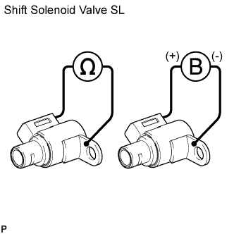
Check the shift solenoid valve SL.
-
Remove the shift solenoid valve SL Click here.
-
Measure the resistance according to the value(s) in the table below.
Standard Resistance Tester Connection Condition Specified Condition Shift solenoid SL connector - Shift solenoid SL body 20°C (68°F) 11 to 15 Ω -
Connect a battery positive (+) lead to the terminal of the solenoid valve connector, and a negative (-) lead to the solenoid body. Then check that the valve moves and makes an operating sound.
OK Valve moves and makes an operating sound.
-
-
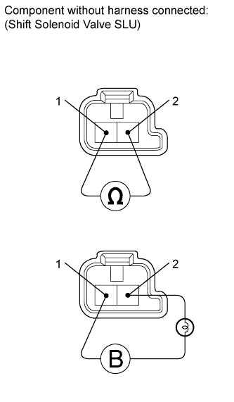
Check the shift solenoid valve SLU.
-
Remove the shift solenoid valve SLU Click here.
-
Measure the resistance according to the value(s) in the table below.
Standard Resistance Tester Connection Condition Specified Condition Terminal 1 of the shift solenoid valve SLU - Terminal 2 20°C (68°F) 5.0 to 5.6 Ω -
Connect a battery positive (+) lead with a 21 W bulb to terminal 2 and a negative (-) lead to terminal 1 of the solenoid valve connector. Then check that the valve moves and makes an operating sound.
OK Valve moves and makes an operating sound.
Result Shift Solenoid Valve Condition Proceed to Shift solenoid valve SL and SLU are OK A Shift solenoid valve SL is NG B Shift solenoid valve SLU is NG C -
B
REPLACE SHIFT SOLENOID VALVE SL Click here
C
REPLACE SHIFT SOLENOID VALVE SLU Click here
A
-
-
INSPECT TRANSMISSION VALVE BODY ASSEMBLY
-
Check the transmission valve body assembly Click here.
OK There are no foreign objects on any valve.
NG
REPAIR OR REPLACE TRANSMISSION VALVE BODY ASSEMBLY Click here
OK
-
-
INSPECT TORQUE CONVERTER CLUTCH ASSEMBLY
-
Check the torque converter clutch assembly Click here.
OK The torque converter clutch operates normally.
NG
REPLACE TORQUE CONVERTER CLUTCH ASSEMBLY
OK 
REPAIR OR REPLACE AUTOMATIC TRANSMISSION ASSEMBLY Click here
-