DYNAMIC RADAR CRUISE CONTROL SYSTEM Distance Control ECU Power Source Circuit
DESCRIPTION
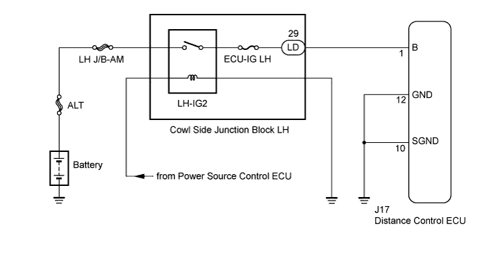
This circuit provides power to operate the distance control ECU. The distance control ECU determines information about the vehicle in front based on data from the radar sensor, and then decides how much acceleration and/or deceleration is needed to maintain the set distance. The distance control ECU also requests the skid control ECU to apply braking and to sound the buzzer.
WIRING DIAGRAM
INSPECTION PROCEDURE
PROCEDURE
-
CHECK DISTANCE CONTROL ECU (B VOLTAGE)
-
Disconnect the distance control ECU connector.
-
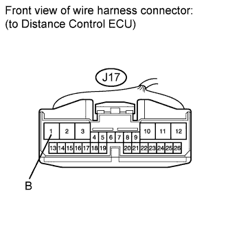
Measure the voltage according to the value(s) in the table below.
Standard Voltage Tester Connection Switch Condition Specified Condition J17-1 (B) - Body ground Engine switch on (IG) 11 to 14 V -
Reconnect the distance control ECU connector.
NG 
CHECK HARNESS AND CONNECTOR (DISTANCE CONTROL ECU - COWL SIDE JUNCTION BLOCK LH) Click here
OK 
-
-
CHECK HARNESS AND CONNECTOR (DISTANCE CONTROL ECU - BODY GROUND)
-
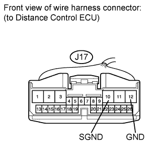
Measure the resistance according to the value(s) in the table below.
Standard Resistance Tester Connection Condition Specified Condition J17-10 (SGND) - Body ground Always Below 1 Ω J17-12 (GND) - Body ground Always Below 1 Ω
NG 
REPAIR OR REPLACE HARNESS OR CONNECTOR
OK 
PROCEED TO NEXT SUSPECTED AREA SHOWN IN PROBLEM SYMPTOMS TABLE Click here
-
-
CHECK HARNESS AND CONNECTOR (DISTANCE CONTROL ECU - COWL SIDE JUNCTION BLOCK LH)
-
Disconnect the LD connector from main body ECU LH (cowl side junction block LH).
-
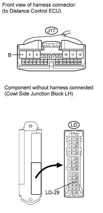
Measure the resistance according to the value(s) in the table below.
Standard Resistance Tester Connection Condition Specified Condition J17-1 (B) - LD-29 Always Below 1 Ω J17-1 (B) or LD-29 - Body ground Always 10 kΩ or higher
NG
REPAIR OR REPLACE HARNESS OR CONNECTOR
OK
GO TO ENTRY AND START SYSTEM Click here
-