DYNAMIC RADAR CRUISE CONTROL SYSTEM TERMINALS OF ECU

-
CHECK DISTANCE CONTROL ECU

Terminal No. (Symbol) Wiring Color Terminal Description Condition Specified Condition J17-1 (B) - J17-12 (GND) B - BR Battery Always 11 to 14 V J17-8 (CANH) - J17-12 (GND) GR- BR CAN communication signal CAN communication circuit Pulse generation J17-9 (CANL) - J17-12 (GND) W - BR CAN communication signal CAN communication circuit Pulse generation J17-10 (SGND) - Body ground BR - Body ground Ground Always Below 1 V J17-12 (GND) - Body ground BR - Body ground Ground Always Below 1 V J17-13 (IGB) - J17-12 (GND) P - BR Engine switch on signal Engine switch off Below 1 V J17-13 (IGB) - J17-12 (GND) P - BR Engine switch on signal Engine switch on (IG) 11 to 14 V J17-16 (MODE) - J17-12 (GND) R - BR Cruise distance switch signal Engine switch on (IG), Cruise distance switch signal ON 0 to 2 V J17-16 (MODE) - J17-12 (GND) R - BR Cruise distance switch signal Engine switch on (IG), Cruise distance switch signal ON 11 to 14 V J17-22 (LRDD) - J17-10 (SGND) O - BR Millimeter wave radar sensor input signal Engine switch on (IG) Pulse generation
(see waveform 1)
J17-23 (LRRD) - J17-10 (SGND) L - BR Millimeter wave radar sensor output signal Engine switch on (IG) Pulse generation
(see waveform 2)
-
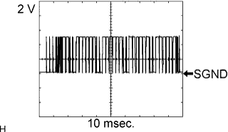
Reference: waveform 1
Tech Tips
-
Terminal: J17-22 (LRDD) - J17-10 (SGND)
-
Gauge set: 2 V/DIV., 10 msec./DIV.
-
Condition: Engine switch on (IG)
-
-
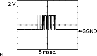
Reference: waveform 2
Tech Tips
-
Terminal: J17-23 (LRRD) - J17-10 (SGND)
-
Gauge set: 2 V/DIV., 5 msec./DIV.
-
Condition: Engine switch on (IG)
-
-
-
CHECK ECM (for 2UR-GSE)
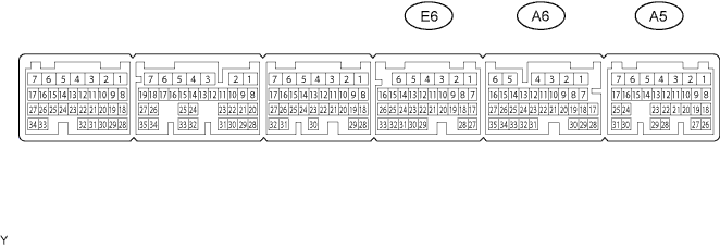
Terminal No. (Symbol) Wiring Color Terminal Description Condition Specified Condition A5-12 (ST1-) - E6-1 (E1) G-W - W-B Stop light signal Engine switch on (IG), Brake pedal depressed (Stop light switch on) Below 1 V A5-12 (ST1-) - E6-1 (E1) G-W - W-B Stop light signal Engine switch on (IG), Brake pedal released (Stop light switch off) 11 to 14 V A5-13 (STP) - E6-1 (E1) R-B - W-B Stop light signal Brake pedal released (Stop light switch off) Below 1 V A5-13 (STP) - E6-1 (E1) R-B - W-B Stop light signal Brake pedal depressed (Stop light switch on) 11 to 14 V A5-16 (LGND) - Body ground B - Body ground Ground Always Below 1 V A5-17 (CCHG) - E6-1 (E1) B-L - W-B Mode signal Engine switch on (IG), Cruise control main switch on, MODE switch on Below 1 V A5-17 (CCHG) - E6-1 (E1) B-L - W-B Mode signal Engine switch on (IG), Cruise control main switch on, MODE switch off 11 to 14 V A6-15 (CCS) - E6-1 (E1) L-B - W-B Cruise control main switch signal Engine switch on (IG) 11 to 14 V A6-15 (CCS) - E6-1 (E1) L-B - W-B Cruise control main switch signal CANCEL switch on 6.6 to 10.1 V A6-15 (CCS) - E6-1 (E1) L-B - W-B Cruise control main switch signal - (COAST)/SET switch on 4.5 to 7.1 V A6-15 (CCS) - E6-1 (E1) L-B - W-B Cruise control main switch signal + (ACCEL)/RES (RESUME) switch on 2.3 to 4.0 V A6-15 (CCS) - E6-1 (E1) L-B - W-B Cruise control main switch signal Main switch on Below 1 V E6-1 (E1) - Body ground W-B - Body ground Ground Always Below 1 V If the value is not within the specified range, the ECM may have a malfunction.