DYNAMIC RADAR CRUISE CONTROL SYSTEM, Diagnostic DTC:P0571

| DTC Code | DTC Name |
|---|---|
| P0571 | Stop Light Switch Circuit Malfunction |
DESCRIPTION
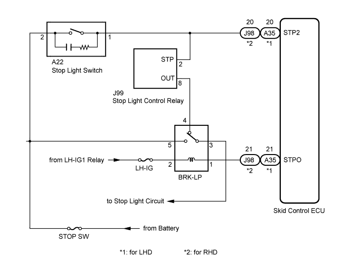
The ECM receives the brake demand signal from the distance control ECU and transmits it to the skid control ECU.
The skid control ECU receives a signal from the ECM and operates the brake actuator.
The skid control ECU operates the brake actuator and at the same time illuminates the stop light by operating the BRK-LP relay.
| DTC No. | DTC Detection Condition | Trouble Area |
|---|---|---|
| P0571 | This trouble code is output when the ECM detects the BRK-LP relay error signal from the skid control ECU for 0.2 sec. or more while the dynamic cruise control is in operation. |
|
WIRING DIAGRAM
INSPECTION PROCEDURE
PROCEDURE
-
CHECK STOP LIGHT OPERATION
-
Check that the stop lights come on when the brake pedal is depressed, and go off when the brake pedal is released.
OK Condition Illumination Condition Brake pedal depressed ON Brake pedal released OFF
NG 
GO TO PROBLEM SYMPTOMS TABLE (STOP LIGHT SYSTEM) Click here
OK 
-
-
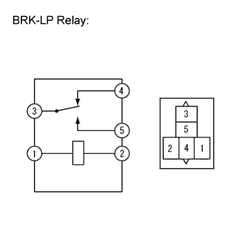
CHECK BRK-LP RELAY
-
Turn the engine switch off.
-
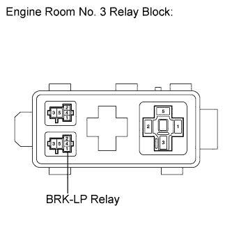
Remove the BRK-LP relay from the engine room No. 3 relay block.
-
Measure the resistance according to the value(s) in the table below.
Standard Resistance Tester Connection Condition Specified Condition 3 - 5 Voltage is not applied between terminals 1 and 2 10 kΩ or higher 3 - 5 Voltage is applied between terminals 1 and 2 Below 1 Ω 3 - 4 Voltage is not applied between terminals 1 and 2 Below 1 Ω 3 - 4 Voltage is applied between terminals 1 and 2 10 kΩ or higher
NG
REPLACE BRK-LP RELAY
OK
-
-
CHECK HARNESS AND CONNECTOR (ENGINE ROOM NO. 3 RELAY BLOCK - BATTERY)
-
Measure the voltage according to the value(s) in the table below.
Standard Voltage Tester Connection Condition Specified Condition BRK LP relay terminal 5 - Body ground Always 11 to 14 V BRK LP relay terminal 2 - Body ground Engine switch on (IG) 11 to 14 V BRK LP relay terminal 2 - Body ground Engine switch off Below 1 V
NG
REPAIR OR REPLACE HARNESS OR CONNECTOR
OK
-
-
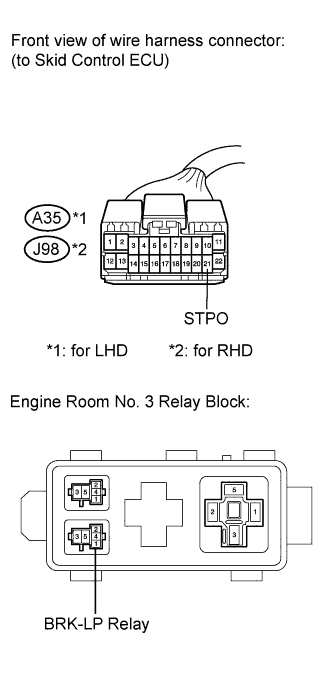
CHECK HARNESS AND CONNECTOR (ENGINE ROOM NO. 3 RELAY BLOCK - SKID CONTROL ECU)
-
Disconnect the connector from the skid control ECU.
-
Measure the resistance according to the value(s) in the table below.
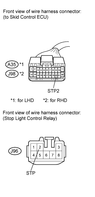
Standard Resistance Tester Connection Condition Specified Condition A35*1, J98*2-21 (STPO) - BRK LP relay terminal 1 Always Below 1 Ω A35*1, J98*2-21 (STPO) - Body ground Always 10 kΩ or higher A35*1, J98*2-20 (STP2) - BRK LP relay terminal 4 Always Below 1 Ω A35*1, J98*2-20 (STP2) - Body ground Always 10 kΩ or higher
-
*1: for LHD
-
*2: for RHD
-
NG
REPAIR OR REPLACE HARNESS OR CONNECTOR
OK
-
-
CHECK HARNESS AND CONNECTOR (STOP LIGHT CONTROL RELAY - SKID CONTROL ECU)
-
Disconnect the connector from the stop light control relay.
-
Measure the resistance according to the value(s) in the table below.
Standard Resistance Tester Connection Condition Specified Condition A35*1, J98*2-20 (STP2) - J96-2 (STP) Always Below 1 Ω A35*1, J98*2-20 (STP2) - Body ground Always 10 kΩ or higher
-
*1: for LHD
-
*2: for RHD
-
NG
REPAIR OR REPLACE HARNESS OR CONNECTOR
OK 
REPLACE SKID CONTROL ECU Click here
-