ENGINE SWITCH REMOVAL

-
DISCONNECT CABLE FROM NEGATIVE BATTERY TERMINAL
Note
When disconnecting the cable, some systems need to be initialized after the cable is reconnected Click here.
-
REMOVE SHIFT LEVER KNOB SUB-ASSEMBLY
-
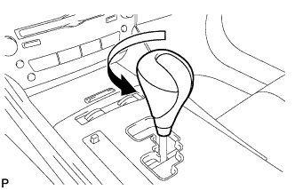
Turn the shift lever knob counterclockwise and remove the shift lever knob sub-assembly.
-
-
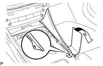
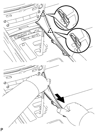
REMOVE UPPER NO. 1 CONSOLE PANEL GARNISH
-
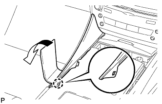
Using a moulding remover, disengage the claw as shown in the illustration.
-
Pull the upper No. 1 console panel garnish in the direction indicated by the arrow to disengage the 2 clips and remove the upper No. 1 console panel garnish.
-
-
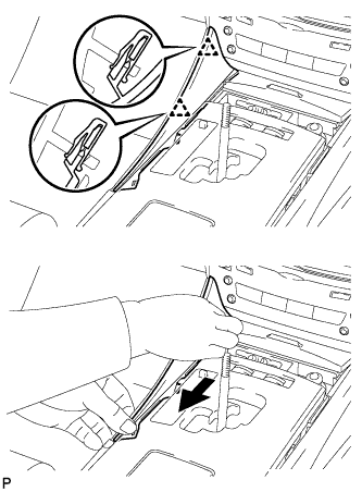
REMOVE UPPER NO. 2 CONSOLE PANEL GARNISH
-
Using a moulding remover, disengage the claw as shown in the illustration.
-
Pull the upper No. 2 console panel garnish in the direction indicated by the arrow to disengage the 2 clips and remove the upper No. 2 console panel garnish.
-
-
REMOVE CONSOLE PANEL SUB-ASSEMBLY
-
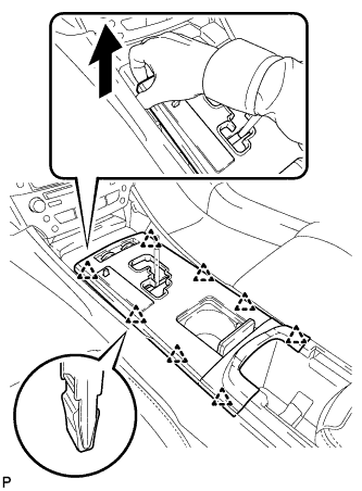
Hold the front of the console panel sub-assembly as shown in the illustration and disengage the 8 clips by pulling the console panel sub-assembly in the direction shown by the arrow.
Note
Do not use any tools to disengage the clips. The use of tools may result in damage to the console panel sub-assembly.
-
Disconnect the connectors and remove the console panel sub-assembly.
-
-
REMOVE INSTRUMENT PANEL BOX ASSEMBLY (w/o Ashtray)
-
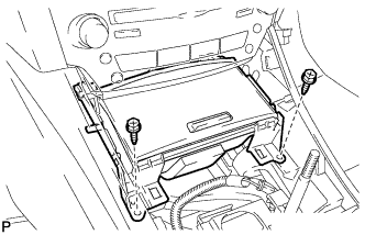
Remove the 2 screws <E>.
-
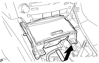
Pull the instrument panel box assembly in the direction indicated by arrow and disconnect the connectors to remove the instrument panel box assembly.
-
-
REMOVE FRONT ASH RECEPTACLE BOX SUB-ASSEMBLY (w/ Ashtray)
-
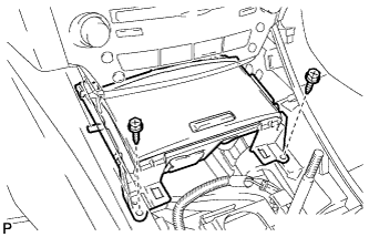
Remove the 2 screws <E>.
-
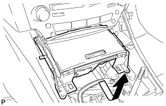
Pull the front ash receptacle box sub-assembly in the direction indicated by the arrow and disconnect the connectors to remove the front ash receptacle box sub-assembly.
-
-
REMOVE REAR ASH RECEPTACLE ASSEMBLY (w/ Ashtray)
-
Remove the rear ash receptacle assembly.
-
-
REMOVE CONSOLE BOX REGISTER ASSEMBLY (w/o Ashtray)
-
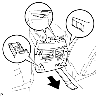
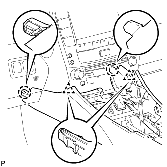
Using a moulding remover, disengage the 2 claws and 4 clips, and remove the console box register assembly as shown in the illustration.
-
-
REMOVE CONSOLE BOX REGISTER ASSEMBLY (w/ Ashtray)
-
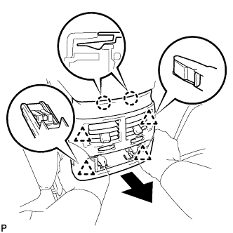
Disengage the 2 claws and 4 clips to remove the console box register assembly.
-
-
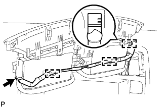
REMOVE CONSOLE BOX
-
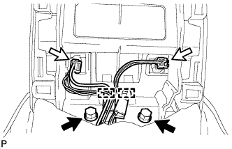
Remove the 2 bolts.
-
Disconnect the 2 connectors.
-
Disengage the 2 clamps.
-
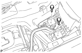
Remove the 2 bolts.
-
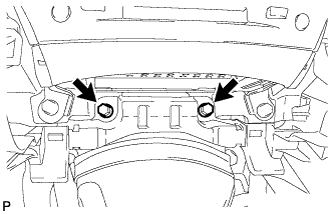
Remove the 2 bolts.
-
Disconnect each connector.
-
Disengage the 2 claws and 2 clips, and then remove the console box.
-
-
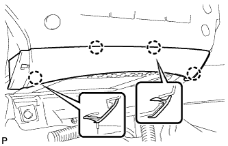
REMOVE NO. 3 INSTRUMENT PANEL REGISTER ASSEMBLY
-
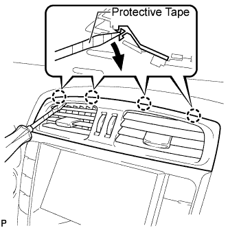
Using a screwdriver, disengage the 4 claws.
Tech Tips
Tape the screwdriver tip before use.
-
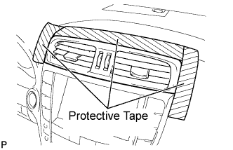
Apply protective tape to the areas shown in the illustration.
-
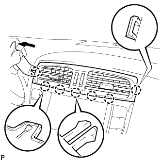
Using a moulding remover, disengage the 4 claws starting from the left of the No. 3 instrument panel register assembly as shown in the illustration. Disengage the remaining 3 claws by pulling the No. 3 instrument panel register assembly by hand.
Note
Do not pry the lower part of the No. 3 instrument panel register assembly. Doing so may damage the assembly.
-
for LHD:
-
Disconnect the connector and remove the No. 3 instrument panel register assembly.
-
-
for RHD:
-
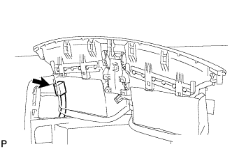
Disengage the 3 clamps.
-
Disconnect the connector and remove the No. 3 instrument panel register assembly.
-
-
-
REMOVE CENTER LOWER INSTRUMENT CLUSTER FINISH PANEL
-
Disengage the 4 claws to remove the center lower instrument cluster finish panel.
-
-
REMOVE MULTI-MEDIA MODULE RECEIVER ASSEMBLY WITH DISPLAY (w/ Multi-display)
-
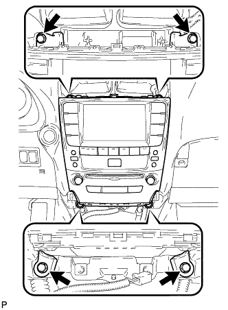
Remove the 4 bolts.
-
Pull the multi-media module receiver assembly with display toward the rear of the vehicle.
-
Disconnect each connector and remove the multi-media module receiver assembly with display.
-
-
REMOVE INTEGRATION CONTROL PANEL WITH RADIO RECEIVER ASSEMBLY (w/o Multi-display)
-
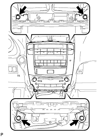
Remove the 4 bolts.
-
Pull the integration control panel with radio receiver assembly toward the rear of the vehicle.
-
Disconnect each connector and remove the panel.
-
-
REMOVE ENGINE SWITCH
-
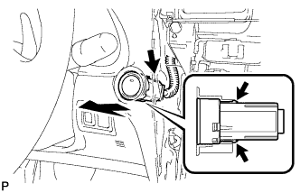
Disconnect the switch connector.
-
Detach the 2 claws and remove the switch.
-