STARTER INSTALLATION

-
INSTALL STARTER ASSEMBLY
-
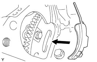
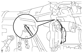
Install the flywheel housing side cover.
-
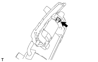
Install the terminal lower cover with the nut.
- Torque:
- 10 N*m { 102 kgf*cm, 7 ft.*lbf }
-
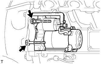
Install the starter assembly with the 2 bolts.
- Torque:
- 37 N*m { 377 kgf*cm, 27 ft.*lbf }
Note
Make sure that the flywheel housing side cover is as shown in the illustration.
-
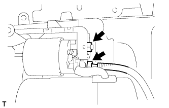
Install the wire harness with the nut.
- Torque:
- 9.8 N*m { 100 kgf*cm, 87 in.*lbf }
-
Connect the starter connector.
-
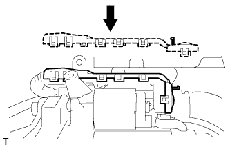
Install the terminal upper cover with the 11 claws.
-
-
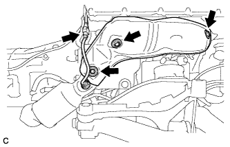
INSTALL NO. 3 EXHAUST MANIFOLD HEAT INSULATOR
-
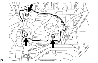
Install the No. 3 exhaust manifold heat insulator with the 3 bolts.
- Torque:
- 10 N*m { 102 kgf*cm, 7 ft.*lbf }
-
-
INSTALL EXHAUST MANIFOLD SUB-ASSEMBLY RH
-
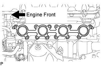
Install a new gasket.
-
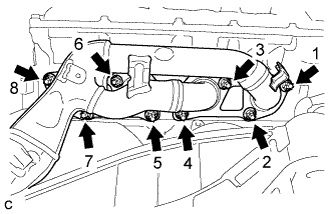
Install the exhaust manifold sub-assembly RH, and install 8 new nuts in the order shown in the illustration.
- Torque:
- 21 N*m { 214 kgf*cm, 16 ft.*lbf }
-
-
INSTALL NO. 1 EXHAUST MANIFOLD HEAT INSULATOR
-
Install the No. 1 exhaust manifold heat insulator with the 3 bolts.
- Torque:
- 10 N*m { 102 kgf*cm, 7 ft.*lbf }
-
Connect the air fuel ratio sensor connector.
-
-
INSTALL OIL LEVEL DIPSTICK GUIDE SUB-ASSEMBLY
-
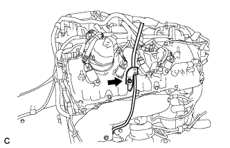
Apply engine oil to a new O-ring, and install it to the oil level dipstick guide sub-assembly.
-
Install the oil level dipstick guide sub-assembly with the bolt.
- Torque:
- 10 N*m { 102 kgf*cm, 7 ft.*lbf }
-
-
INSTALL OIL LEVEL DIPSTICK SUB-ASSEMBLY
-
Install the oil level dipstick sub-assembly.
-
-
INSTALL ENGINE AND TRANSMISSION