OIL PUMP REMOVAL

-
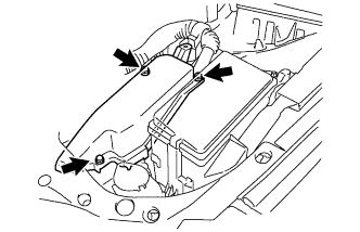
REMOVE V-BANK COVER SUB-ASSEMBLY
-
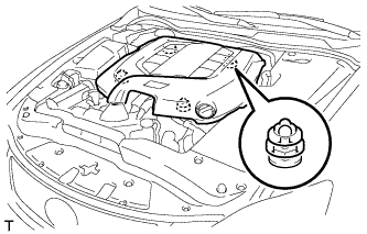
Hold the front of the V-bank cover sub-assembly and raise it to disengage the 2 clips on the front of the cover. Continue to raise the cover to disengage the 2 clips on the rear of the cover and remove the V-bank cover sub-assembly.
Note
Attempting to disengage both front and rear clips at the same time may cause the cover to break.
-
-
REMOVE COOL AIR INTAKE DUCT SEAL
-
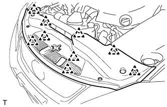
Remove the 9 clips and cool air intake duct seal.
-
-
REMOVE ENGINE ROOM SIDE COVER LH (for LHD)
-

Remove the 5 clips and engine room side cover LH.
-
-
REMOVE ENGINE ROOM SIDE COVER LH (for RHD)
-
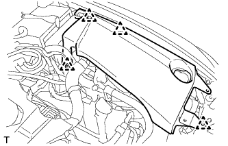
Remove the 4 clips and engine room side cover LH.
-
-
REMOVE ENGINE ROOM SIDE COVER RH (for LHD)
-
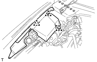
Remove the 3 clips and engine room side cover RH.
-
-
REMOVE ENGINE ROOM SIDE COVER RH (for RHD)
-
Remove the 4 clips and engine room side cover RH.
-
-
DISCHARGE FUEL SYSTEM PRESSURE
-
DISCHARGE REFRIGERANT FROM REFRIGERATION SYSTEM
-
Start up the engine.
-
Turn the A/C switch on.
-
Operate the cooler compressor at an engine speed of approximately 1000 rpm for 5 to 6 minutes to circulate the refrigerant and collect the compressor oil remaining in each component into the cooler compressor.
-
Stop the engine.
-
Recover the refrigerant from the A/C system using a refrigerant recovery unit.
-
-
DISCONNECT CABLE FROM NEGATIVE BATTERY TERMINAL
Note
When disconnecting the cable, some systems need to be initialized after the cable is reconnected Click here.
-
REMOVE ENGINE UNDER COVER
-
REMOVE NO. 2 ENGINE UNDER COVER
-
DRAIN ENGINE OIL
-
Remove the oil filler cap.
-
Remove the oil pan drain plug and drain the engine oil into a container.
-
Install a new gasket and the oil pan drain plug.
- Torque:
- 40 N*m { 408 kgf*cm, 30 ft.*lbf }
-
-
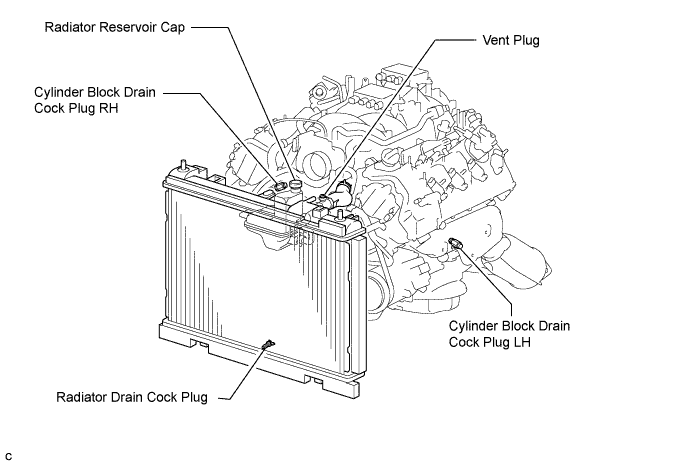
DRAIN ENGINE COOLANT
-
Loosen the radiator drain cock plug.
CAUTION:
Do not loosen the radiator drain cock plug while the engine and radiator are still hot. Pressurized, hot engine coolant and steam may be released and cause serious burns.
Tech Tips
Collect the coolant in a container and dispose of it according to local regulations.
-
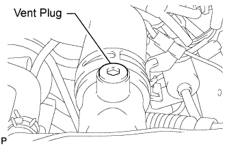
Remove the radiator reservoir cap, and using a 6 mm socket hexagon wrench, remove the vent plug.
-
Drain coolant.
-
Loosen the 2 cylinder block drain cock plugs.
-
-
DRAIN AUTOMATIC TRANSMISSION FLUID
-
Remove the drain plug and gasket, and drain the ATF.
-
Install a new gasket and the drain plug.
- Torque:
- 20 N*m { 204 kgf*cm, 15 ft.*lbf }
-
-
REMOVE NO. 1 AIR CLEANER INLET
-
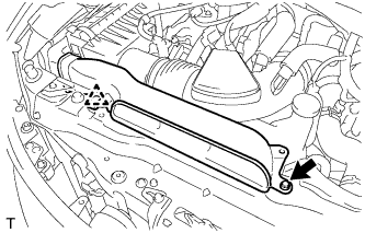
Remove the bolt, clip and No. 1 air cleaner inlet.
-
-
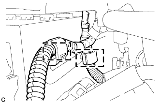
REMOVE AIR CLEANER CAP SUB-ASSEMBLY
-
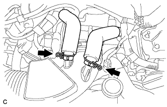
Loosen the 2 hose clamps and separate the 2 ventilation hoses.
-
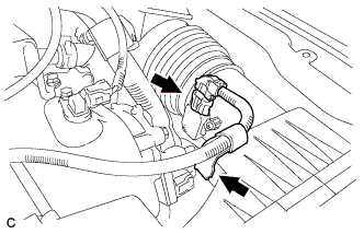
Disconnect the mass air flow meter connector and separate the wire harness clamp.
-
Loosen the hose clamp and separate the air cleaner hose.
-
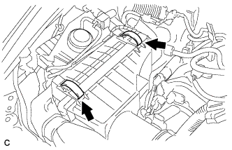
Unlock the 2 clamps and remove the air cleaner cap sub-assembly.
-
-
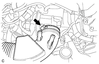
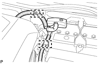
REMOVE AIR CLEANER CASE SUB-ASSEMBLY
-
Remove the 2 clamps and disconnect the vacuum hose.
-
Remove the clamp and disconnect the vacuum switching valve connector.
-
Remove the 2 bolts and air cleaner case sub-assembly.
-
-
REMOVE RADIATOR ASSEMBLY
-
REMOVE BATTERY (for LHD)
-
Disconnect the 2 clamps.
-
Disconnect the cable from the positive (+) battery terminal.
-
Remove the nut and the battery clamp.
-
Remove the battery insulator.
-
Remove the battery.
-
-
REMOVE BATTERY (for RHD)
-
Disconnect the 2 clamps.
-
Disconnect the cable from the positive (+) battery terminal.
-
Remove the nut and the battery clamp.
-
Remove the battery insulator.
-
Remove the battery.
-
-
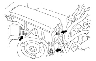
REMOVE NO. 1 BATTERY TRAY SUPPORT
-
REMOVE POWER STEERING ECU ASSEMBLY
-
Release the locks of the 2 power steering ECU assembly connectors (A) and (B).
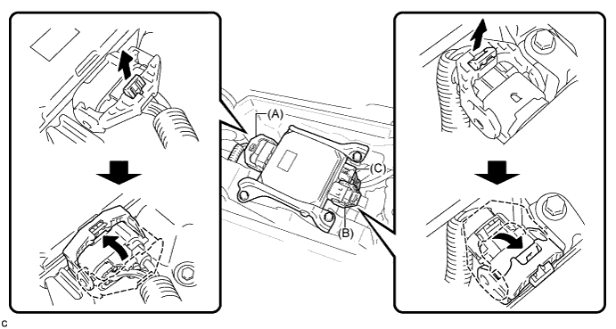
-
Disconnect the connectors (A), (B) and (C) from the power steering ECU assembly.
-
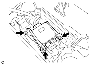
Remove the 3 bolts.
-
Remove the power steering ECU assembly.
-
-
REMOVE BATTERY TRAY (for LHD)
-
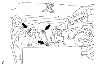
Remove the 3 bolts and battery tray.
-
Remove the 2 bolts and nut and separate the No. 7 engine room relay block.
-
-
REMOVE BATTERY TRAY (for RHD)
-
Remove the 3 bolts and battery tray.
-
Remove the 2 bolts and nut and separate the No. 7 engine room relay block.
-
-
REMOVE WIRE HARNESS CLAMP BRACKET (for LHD)
-
Remove the bolt and separate the wire harness clamp bracket.
-
Separate the wire harness clamp from the wire harness clamp bracket.
-
-
REMOVE WIRE HARNESS CLAMP BRACKET (for RHD)
-
Remove the bolt and separate the wire harness clamp bracket.
-
Separate the wire harness clamp from the wire harness clamp bracket.
-
-
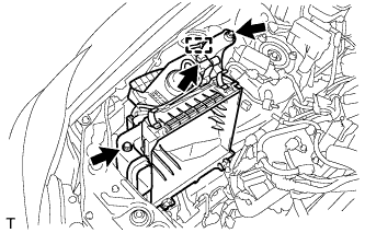
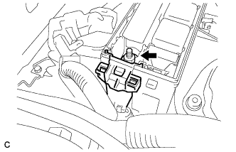
REMOVE ENGINE ROOM ECU COVER
-
Remove the 3 bolts and the engine room ECU cover.
Note
-
Remove all water from on and around the engine room ECU cover.
-
Perform the inspection indoors to avoid rain.
-
Be sure to prevent water intrusion to the ECM (connectors and screw holes).
-
-
-
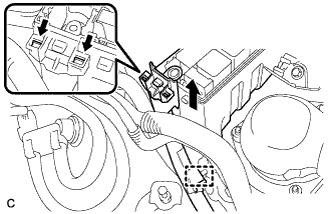
DISCONNECT WIRE HARNESS
-
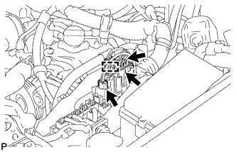
Remove the 3 connectors and connector clamp.
-
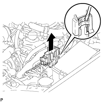
Using a screwdriver, detach the claw and disconnect the No. 4 connector holder.
-
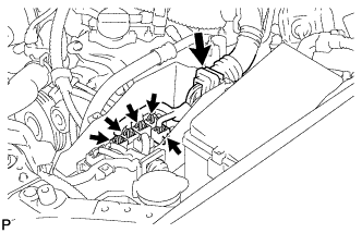
Disconnect the 5 connectors and grommet from the engine room ECU box.
-
Disconnect the 8 connectors and 3clamps.
-
Disconnect the 5 connectors and 7clamps.
-
Remove the 2 bolts and disconnect the 2 ground wires.
-
Remove the No. 1 engine room relay block cover (for RHD).
-
Remove the nut (for RHD).
-
Disconnect the clamp, detach the 2 claws and disconnect the wire harness from the engine room No. 1 relay block (for RHD).
-
Remove the bolt, and disconnect the ground cable.
-
Remove the bolt, and disconnect the clamp and ground cable.
-
-
REMOVE FUEL PUMP ASSEMBLY (for Bank 1)
-
REMOVE FUEL PUMP ASSEMBLY (for Bank 2)
-
REMOVE FUEL PUMP SPACER
-
Remove the 2 fuel pimp spacers.
-
-
REMOVE V-RIBBED BELT
-
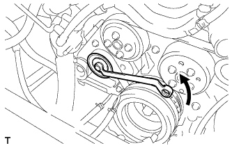
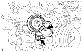
Rotate the V-ribbed belt tensioner pulley counterclockwise to loosen the V-ribbed belt tensioner.
Tech Tips
The pulley bolt for the V-ribbed belt tensioner is reverse threaded.
-
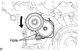
While turning the V-ribbed belt tensioner counterclockwise, align the holes. Insert a bar of φ5 mm (0.197 in.) into the holes to secure the V-ribbed belt tensioner in place.
-
Remove the V-ribbed belt.
-
-
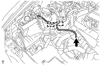
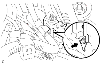
DISCONNECT NO. 1 COOLER REFRIGERANT SUCTION HOSE
-
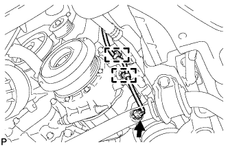
Disconnect the connector and 2 clamps.
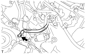
-
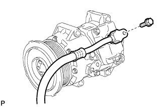
Remove the bolt and disconnect the No. 1 cooler refrigerant suction hose from the compressor.
-
Remove the O-ring from the cooler refrigerant suction hose.
Note
Seal the openings of the disconnected parts using vinyl tape to prevent moisture and foreign matter from entering.
-
-
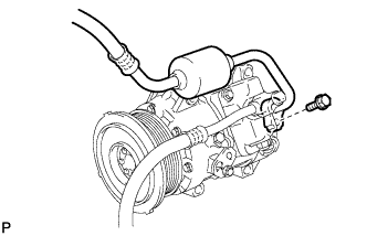
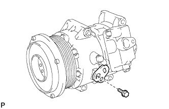
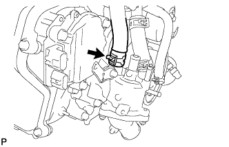
DISCONNECT DISCHARGE HOSE SUB-ASSEMBLY
-
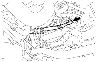
Remove the bolt and disconnect the discharge sub-assembly from the compressor.
-
Remove the O-ring from the discharge sub-assembly.
Note
Seal the openings of the disconnected parts using vinyl tape to prevent moisture and foreign matter from entering.
-
-
SEPARATE COMPRESSOR AND PULLEY
-
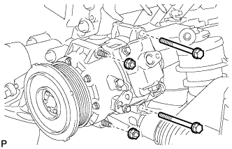
Remove the 2 bolts and 2 nuts.
-
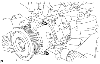
Using an E8 "TORX" socket, remove the 2 stud bolts and compressor.
Tech Tips
Remove the compressor and pulley from the vehicle with the stud bolts remaining in the compressor.
-
Remove the bolt and bracket.
-
-
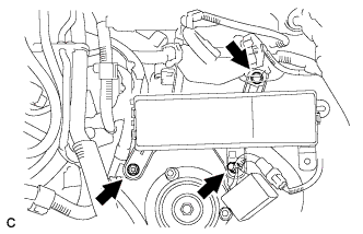
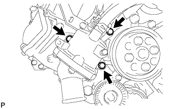
REMOVE GENERATOR ASSEMBLY
-
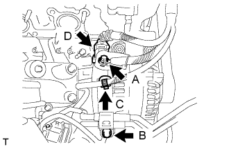
Remove nut A, and disconnect the harness from the +B terminal.
-
Remove bolt B, and disconnect the oil cooler tube.
-
Remove clamp C.
-
Disconnect generator connector D.
-
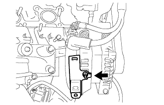
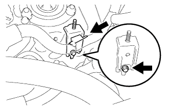
Remove the nut and the wire harness bracket.
-
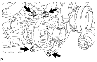
Remove the 2 bolts and 2 nuts.
-
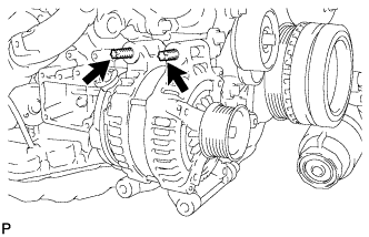
Using an E8 "TORX" socket wrench, remove the 2 stud bolts and generator.
-
-
REMOVE NO. 2 IDLER PULLEY SUB-ASSEMBLY
-
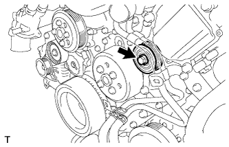
Remove the bolt and idler pulley sub-assembly.
-
-
REMOVE OIL PUMP DRIVE SHAFT PULLEY
-
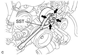
Using SST, hold the oil pump drive shaft pulley.
- SST
- 09960-10010 ( 09962-01000, 09963-00600 )
-
Remove the 4 bolts and oil pump drive shaft pulley.
-
-
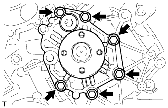
REMOVE WATER PUMP PULLEY
-
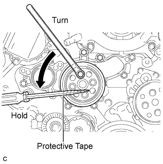
Using a screwdriver or an equivalent, hold the water pump pulley.
Tech Tips
Tape the screwdriver tip before use to avoid damage.
-
Remove the 4 bolts and water pump pulley.
-
-
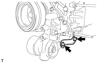
DISCONNECT NO. 2 RADIATOR HOSE
-
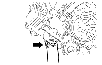
Disconnect the No. 2 radiator hose from the water inlet housing.
-
-
DISCONNECT NO. 5 WATER BY-PASS HOSE
-
Disconnect the No. 5 water by-pass hose from the water inlet housing.
-
-
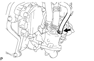
DISCONNECT WATER INLET HOSE
-
Disconnect the water inlet hose from the water inlet housing.
-
-
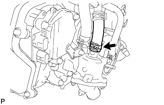
DISCONNECT NO. 3 WATER BY-PASS HOSE
-
Disconnect the No. 3 water by-pass hose from the water inlet housing.
-
-
REMOVE WATER INLET HOUSING
-
Remove the 3 bolts, water inlet housing and gasket.
-
-
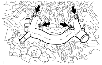
REMOVE NO. 2 WATER BY-PASS PIPE SUB-ASSEMBLY
-
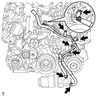
Remove the 3 hose clamps and disconnect the 3 water by-pass hoses.
-
Remove the 4 bolts and No. 2 water by-pass pipe sub-assembly.
-
-
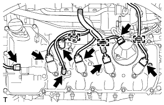
REMOVE IGNITION COIL ASSEMBLY
-
Disconnect the 8 ignition coil connectors.
-
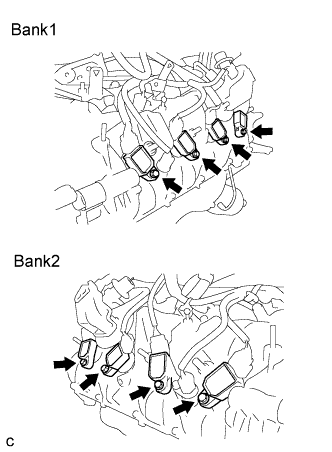
Remove the 8 bolts and 8 ignition coil assemblies.
Note
Do not damage the ignition coil assemblies when removing them.
-
-
REMOVE NO. 4 V-BANK COVER BRACKET SUB-ASSEMBLY
-
Remove the nut and No. 4 V-bank cover bracket.
-
-
REMOVE NO. 3 V-BANK COVER BRACKET SUB-ASSEMBLY
-
Remove the bolt and No. 3 V-bank cover bracket.
-
-
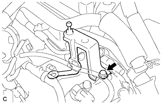
REMOVE FRONT WATER BY-PASS JOINT
-
Remove the 4 nuts, front water by-pass joint and 2 gaskets.
-
-
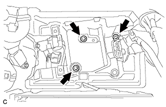
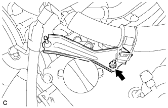
REMOVE OIL FILTER BRACKET SUB-ASSEMBLY
-
Remove the 2 bolts and oil filter bracket stay.
-
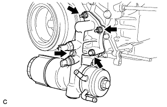
Remove the 2 bolts, 2 nuts and oil filter bracket sub-assembly.
-
Remove the 2 gaskets from the oil filter bracket sub-assembly.
-
-
REMOVE CRANKSHAFT PULLEY
-
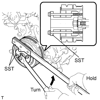
Using SST, loosen the crankshaft pulley set bolt.
- SST
- 09213-38010
- 09330-00021
Tech Tips
Loosen the crankshaft pulley set bolt until 2 to 3 threads remain threaded to the crankshaft.
-
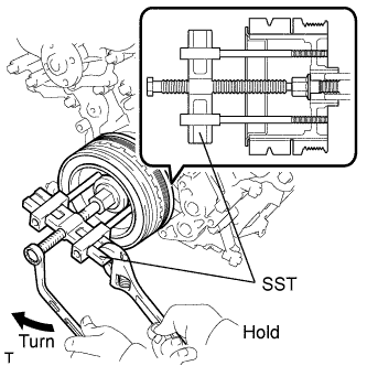
Using the pulley set bolt and SST, remove the crankshaft pulley.
- SST
- 09950-50013 ( 09951-05010, 09952-05010, 09953-05010, 09954-05031 )
Tech Tips
Apply grease to the threads and tip of the SST center bolt.
-
-
REMOVE CRANKSHAFT TIMING GEAR KEY
-
Remove the crankshaft timing gear key from the crankshaft.
-
-
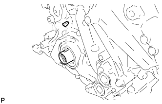
REMOVE TIMING GEAR CASE OR TIMING CHAIN CASE OIL SEAL
-
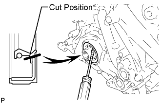
Using a knife, cut through the oil seal lip.
-
Using a screwdriver with its tip taped, pry out the oil seal.
Note
After removal, check the crankshaft for damage. If it is damaged, smooth the surface with 400-grit sandpaper.
-
-
REMOVE CYLINDER HEAD COVER SUB-ASSEMBLY LH (for Bank 1)
-
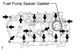
Remove the fuel pump spacer gasket.
-
Remove the 16 bolts, 3 seal washers, cylinder head cover sub-assembly LH and cylinder head cover gasket LH.
Tech Tips
Make sure that the removed parts are returned to the original places they were removed from.
-
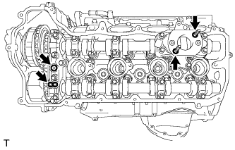
Remove the 2 oil hole gaskets and 2 O-rings from the camshaft bearing caps.
-
-
REMOVE CYLINDER HEAD COVER SUB-ASSEMBLY (for Bank 2)
-
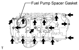
Remove the fuel pump spacer gasket.
-
Remove the 16 bolts, 3 seal washers, cylinder head cover sub-assembly and cylinder head cover gasket.
Tech Tips
Make sure that the removed parts are returned to the original places they were removed from.
-
Remove the 2 oil hole gaskets and 2 O-rings from the camshaft bearing caps.
-
-
REMOVE SPARK PLUG TUBE GASKET
-
Using a screwdriver, pry out the 8 spark plug tube gaskets from the each cylinder head sub-assembly.
Tech Tips
Tape the screwdriver tip before use.
-
-
REMOVE V-RIBBED BELT TENSIONER ASSEMBLY
-
Remove the standard bolt, 6 mm hexagon bolt and V-ribbed belt tensioner assembly.
-
-
REMOVE CAMSHAFT TIMING CONTROL MOTOR ASSEMBLY LH (for Bank 1)
-
Remove the 3 bolts and the camshaft timing control motor assembly LH.
-
Remove the O-ring from the camshaft timing control motor assembly LH.
-
-
REMOVE CAMSHAFT TIMING CONTROL MOTOR ASSEMBLY RH (for Bank 2)
-
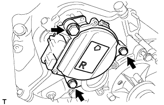
Remove the 3 bolts and the camshaft timing control motor assembly RH.
-
Remove the O-ring from the camshaft timing control motor assembly RH.
-
-
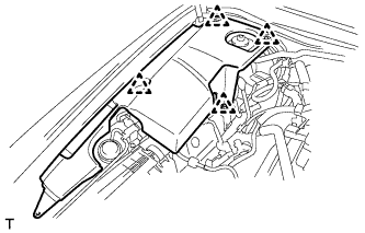
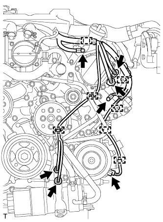
REMOVE TIMING CHAIN COVER SUB-ASSEMBLY
-
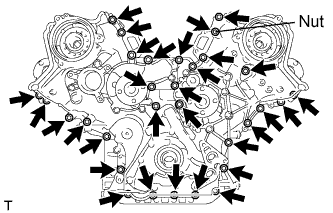
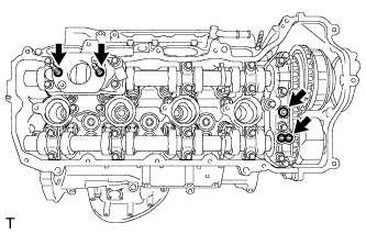
Remove the 30 bolts and nut shown in the illustration.
-
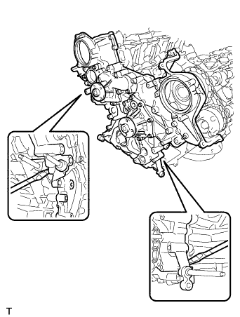
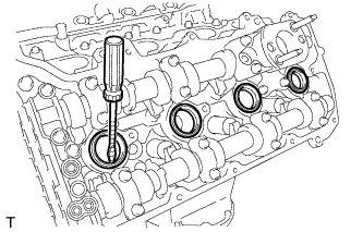
Remove the timing chain cover sub-assembly by prying between the timing chain cover sub-assembly and cylinder head and cylinder block with a screwdriver as shown in the illustration.
Note
Be careful not to damage the contact surfaces of the cylinder head, cylinder block and chain cover.
Tech Tips
Tape the screwdriver tip before use.
-

Remove the oil pump gasket from the cylinder block.
-
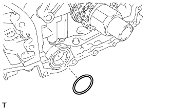
Remove the O-ring from the cylinder block.
-
-
REMOVE INLET WATER PIPE
-
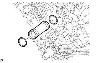
Remove the inlet water pipe.
-
Remove the 2 O-rings from the inlet water pipe.
-
-
REMOVE NO. 1 OIL PIPE
-
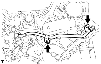
Remove the 2 bolts and No. 1 oil pipe.
-
Remove the oil pipe seal and O-ring from the No. 1 oil pipe.
-
-
REMOVE NO. 2 OIL PIPE
-
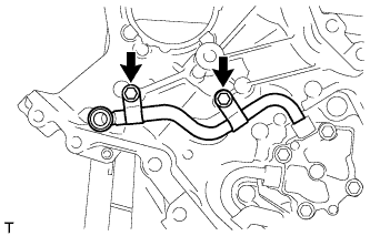
Remove the 2 bolts and No. 2 oil pipe.
-
Remove the oil pipe seal and O-ring from the No. 2 oil pipe.
-
-
REMOVE NO. 3 OIL PIPE
-
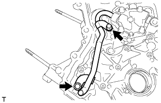
Remove the 2 bolts and No. 3 oil pipe.
-
Remove the O-ring from the No. 3 oil pipe.
-
-
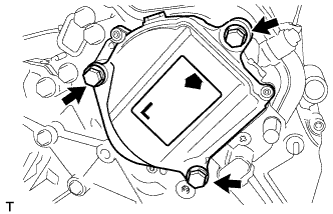
REMOVE SCAVENGING PUMP ASSEMBLY
-
Remove the 6 bolts, scavenging pump assembly and gasket.
-