RADIATOR INSTALLATION

-
INSTALL LOWER RADIATOR SUPPORT
-
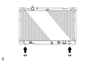
Install the 2 lower radiator supports to the radiator assembly.
-
-
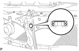
INSTALL RADIATOR SUPPORT CUSHION
-
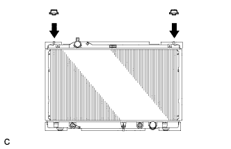
Install the 2 radiator support cushions to the radiator assembly.
-
-
INSTALL RADIATOR ASSEMBLY
-
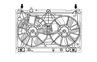
Install the fan assembly to the radiator with the 2 guides at the bottom and claw on the top.
-
Install the 2 bolts.
- Torque:
- 5.0 N*m { 51 kgf*cm, 44 in.*lbf }
-
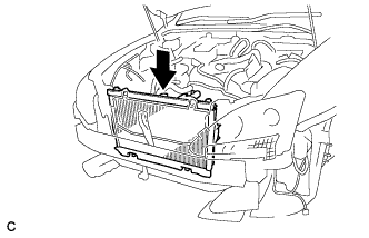
Install the radiator assembly to the vehicle together with the cooling fan assembly.
Note
Make sure that the cooler condenser assembly and radiator assembly do not come into contact with each other.
-
-
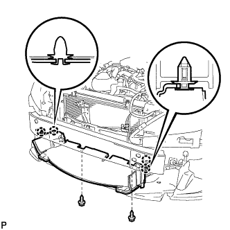
INSTALL COOLER CONDENSER ASSEMBLY
-
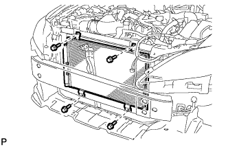
Install the cooler condenser assembly with the 4 bolts.
- Torque:
- 5.0 N*m { 51 kgf*cm, 44 in.*lbf }
-
-
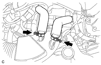
CONNECT OIL COOLER HOSE
-
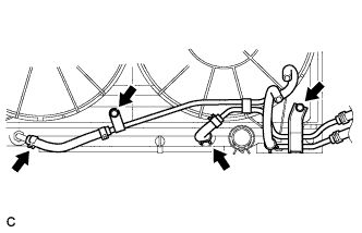
Install the oil cooler pipe with the 2 bolts.
- Torque:
- 5.5 N*m { 56 kgf*cm, 49 in.*lbf }
-
Connect the 2 oil cooler hoses to the radiator assembly.
-
-
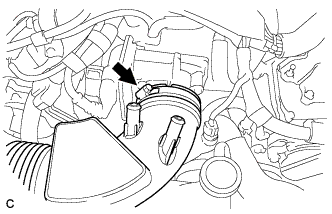
CONNECT NO. 2 RADIATOR HOSE
-
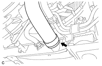
Connect the No. 2 radiator hose to the radiator assembly.
-
-
CONNECT NO. 1 RADIATOR HOSE
-
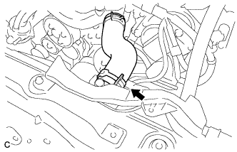
Connect the No. 1 radiator hose to the radiator assembly.
-
-
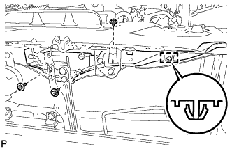
INSTALL UPPER RADIATOR SUPPORT
-
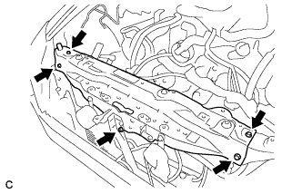
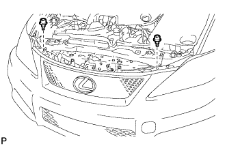
Install the 5 bolts and the upper radiator support.
- Torque:
- 8.0 N*m { 82 kgf*cm, 71 in.*lbf }
-
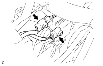
Connect the 2 cooling fan ECM connectors.
-
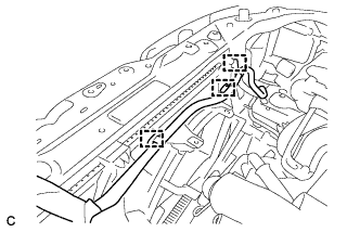
Install the 3 clamps and the wire harness to the fan shroud.
-
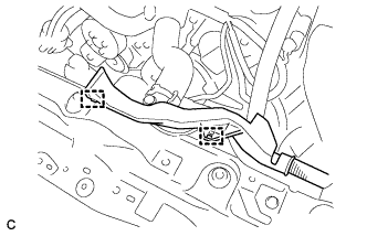
Install the 2 clamps and the wire harness to the upper radiator support.
-
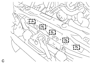
Install the 5 clamps and the wire harness to the upper radiator support.
-
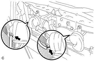
Connect the 2 horn connectors.
-
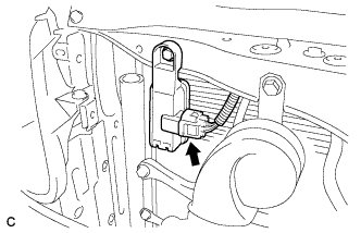
Connect the smog ventilation sensor connector.
-
-
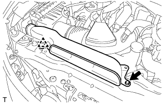
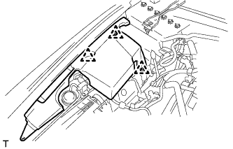
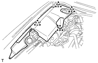
INSTALL ENGINE ROOM ECU OUTLET DUCT
-
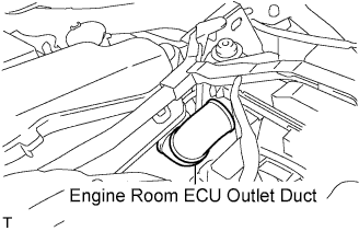
Install the engine room ECU outlet duct to the engine room ECU box.
-
-
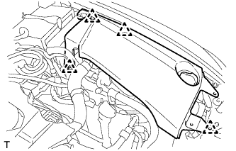
INSTALL RADIATOR RESERVE TANK ASSEMBLY
-
Install the radiator reserve tank assembly with the 2 bolts and 2 reserve tank hoses.
- Torque:
- 5.0 N*m { 51 kgf*cm, 44 in.*lbf }
-
-
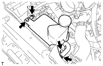
INSTALL HOOD LOCK ASSEMBLY
-
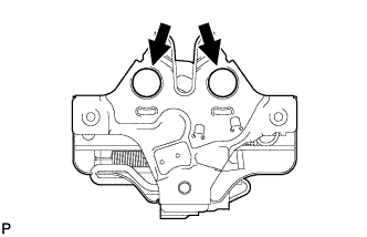
Apply MP grease to the sliding areas of the hood lock assembly.
-
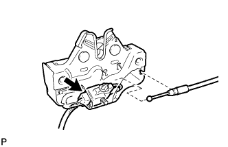
Connect the hood lock control cable assembly and connector.
-
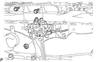
Install the hood lock assembly with the 2 bolts and hood lock nut.
- Torque:
- 8.0 N*m { 82 kgf*cm, 71 in.*lbf }
-
-
INSTALL HOOD LOCK NUT CAP
-
Install a new hood lock nut cap.
-
-
INSTALL HOOD LOCK CONTROL CABLE COVER
-
Engage the clamp.
-
Install the hood lock control cable cover with the 3 screws.
-
-
INSTALL MILLIMETER WAVE RADAR SENSOR ASSEMBLY (w/ Dynamic Radar Cruise Control System)
-
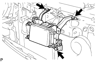
Install the millimeter wave radar sensor with the 3 bolts.
- Torque:
- 5.5 N*m { 56 kgf*cm, 49 in.*lbf }
-
Connect the connector.
-
-
INSTALL AIR CLEANER CAP SUB-ASSEMBLY
-
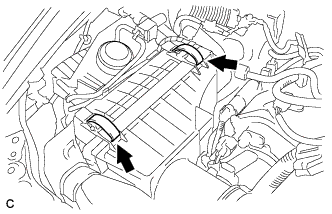
Install the air cleaner cap sub-assembly with air cleaner hose and lock the 2 clamps.
Tech Tips
Tightening torque for the hose clamp located between the air cleaner cap sub-assembly and air cleaner hose assembly is as follows.
- Torque:
- 4.0 N*m { 41 kgf*cm, 35 in.*lbf }
-
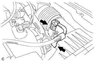
Connect the air cleaner hose to the throttle body with the hose clamp.
- Torque:
- 4.0 N*m { 41 kgf*cm, 35 in.*lbf }
-
Connect the 2 ventilation hoses with the 2 hose clamps.
-
Connect the mass air flow meter connector and wire harness clamp.
-
-
INSTALL NO. 1 AIR CLEANER INLET
-
Install the No. 1 air cleaner inlet with the bolt and clip.
- Torque:
- 5.0 N*m { 51 kgf*cm, 44 in.*lbf }
-
-
INSTALL RADIATOR SUPPORT OPENING COVER
-
Engage the 4 clips and install the radiator support opening cover.
-
Install the 2 screws.
-
-
INSTALL FRONT BUMPER ENERGY ABSORBER
-
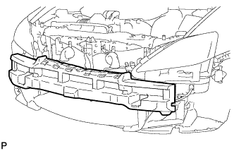
Install the front bumper energy absorber.
-
-
INSTALL FRONT BUMPER ASSEMBLY
-
Connect the 2 fog light connectors.
-
Connect the headlight cleaner hose to the windshield washer jar and pump assembly.
-
w/ LEXUS Parking Assist-Sensor system:
-
Connect the ultrasonic sensor connector.
-
-
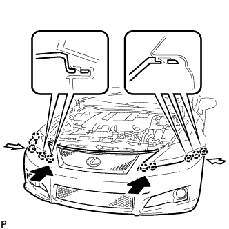
Engage the 10 claws and install the front bumper assembly.
-
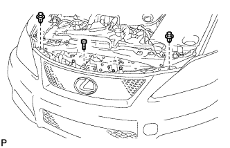
Install the 2 clips and screw.
-
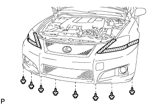
Install the 8 screws.
-
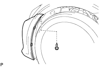
Install the screw.
Tech Tips
Use the same procedure for the RH side and LH side.
-
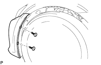
Install the 2 pin hold clips.
Tech Tips
Use the same procedure for the RH side and LH side.
-
-
INSTALL RADIATOR GRILLE PROTECTOR
-
Install the 2 radiator grille protectors.
-
-
ADD AUTOMATIC TRANSMISSION FLUID
-
ADD ENGINE COOLANT
Note
Before adding coolant, turn the A/C switch OFF.
Total capacity 11.9 liters (12.6 US qts, 10.5 Imp. qts)
-
Tighten the radiator drain cock plug by hand.
-
Tighten the 2 cylinder block drain cock plugs.
- Torque:
- 13 N*m { 133 kgf*cm, 10 ft.*lbf }
-
Add TOYOTA Super Long Life Coolant (SLLC) into the radiator reservoir.
Capacity Approximately 5.0 liters (5.3 US qts, 4.4 Imp. qts) Tech Tips
-
LEXUS vehicles are filled with TOYOTA SLLC at the factory. In order to avoid damage to the engine cooling system and other technical problems, only use TOYOTA SLLC or similar high quality ethylene glycol based non-silicate, non-amine, non-nitrite, non-borate coolant with long-life hybrid organic acid technology (coolant with long-life hybrid organic acid technology consists of a combination of low phosphates and organic acids).
-
Contact any authorized LEXUS dealer or repairer or another duly qualified and equipped professional for further details.
-
Thermostat opening timing can be confirmed by squeezing the inlet radiator hose and sensing vibrations when the coolant starts to flow inside the hose.
-
-
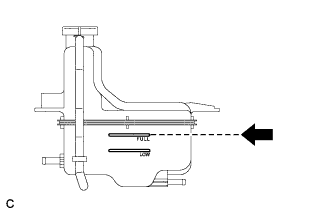
Further add coolant into the reservoir until it reaches the FULL line.
-
Squeeze the No. 1 and No. 2 radiator hoses several times, and then check the coolant level.
If the coolant level is low, add coolant.
-
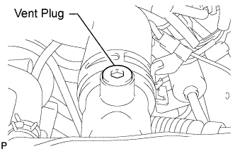
Using a 6 mm socket hexagon wrench, install the vent plug.
- Torque:
- 1.5 N*m { 15 kgf*cm, 13 in.*lbf }
-
Bleed air from the cooling system.
Note
Before starting the engine, turn the A/C switch off.
-
While idling the engine for approximately 10 minutes, make sure that the coolant remains at the FULL line by adding coolant as necessary.
-
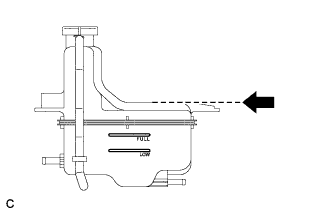
After idling the engine for 10 minutes, add coolant to the level shown in the illustration.
Capacity Approximately 2.5 to 3.5 liters (2.6 to 3.7 US qts, 2.2 to 3.1 Imp.qts) -
Close the radiator reservoir cap, and run the engine at 1500 to 2000 rpm for 5 minutes.
Tech Tips
Thermostat opening timing can be confirmed by squeezing the No. 1 radiator hose and sensing vibrations when the SLLC starts to flow inside the hose.
CAUTION:
When squeezing the radiator hose:
-
Wear protective gloves.
-
Be careful as the radiator hose is hot.
-
Keep your hands away from the radiator fan.
-
-
-
Stop the engine and wait until the coolant cools down to ambient temperature.
CAUTION:
Do not remove the radiator reservoir cap while the engine and radiator are still hot. Pressurized, hot coolant and steam may be released and cause serious burns.
-
Check the coolant level.
If the coolant level is below the FULL line, add coolant until it reaches the FULL line.
-
-
INSPECT FOR COOLANT LEAK
Note
Before performing each inspection, turn the A/C switch OFF.
CAUTION:
Do not remove the radiator reservoir cap while the engine and radiator are still hot. Pressurized, hot engine coolant and steam may be released and cause serious burns.
-
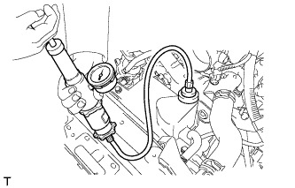
Fill the radiator with coolant and attach a radiator cap tester.
-
Warm up the engine.
-
Using the radiator cap tester, increase the pressure inside the radiator to 118 kPa (1.2 kgf/cm2, 17 psi), and check that the pressure does not drop.
If the pressure drops, check the hoses, radiator and water pump for leaks. If no external leaks are found, check the heater core, cylinder block and head.
-
-
INSTALL ENGINE UNDER COVER
-
INSTALL NO. 2 ENGINE UNDER COVER
-
INSTALL V-BANK COVER SUB-ASSEMBLY
-
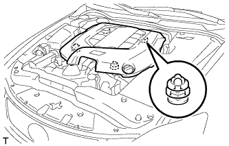
Engage the 4 clips to install the V-bank cover sub-assembly.
Note
-
Be sure to engage the clips securely.
-
Do not apply excessive force or hit the cover to engage the clips. This may cause the cover to break.
-
-
-
INSTALL ENGINE ROOM SIDE COVER RH (for LHD)
-
Install the engine room side cover RH with the 3 clips.
-
-
INSTALL ENGINE ROOM SIDE COVER RH (for RHD)
-
Install the engine room side cover RH with the 4 clips.
-
-
INSTALL ENGINE ROOM SIDE COVER LH (for LHD)
-

Install the engine room side cover LH with the 5 clips.
-
-
INSTALL ENGINE ROOM SIDE COVER LH (for RHD)
-
Install the engine room side cover LH with the 4 clips.
-
-
INSTALL COOL AIR INTAKE DUCT SEAL
-
Install the cool air intake duct seal with the 9 clips.
-
-
ADJUST MILLIMETER WAVE RADAR SENSOR ASSEMBLY (w/ Dynamic Radar Cruise Control System)
CAUTION:
Exposure to radio frequency emissions is hazardous to your health. It is hazardous to your health to be within 20 cm (7.87 in.) of the device's radio frequency aperture.
Note
-
This device complies with FCC radio frequency emission regulations.
-
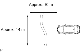
Perform measurements on a level surface.
-
Make sure that no large pieces of metal are within a 10 m (32.81 ft.) x 14 m (45.93 ft.) area in front of the vehicle. If possible, the surrounding area should also be free of large metal objects.
-
Before adjusting the radar beam axis, prepare the vehicle as follows:
-
Check the tire pressure and adjust it if necessary.
-
Remove all excess weight from the vehicle (luggage, heavy objects, etc.).
-
-
Check and adjust the vertical direction of the radar sensor.
-
Remove dust, oil, and foreign matter from the radar sensor's level rack.
-
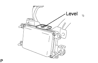
Set a level on the radar sensor's level rack.
-
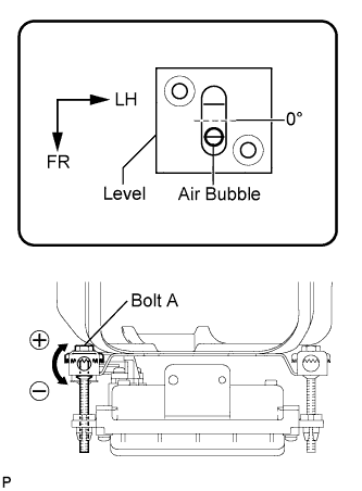
Check that the air bubble is within the red frame on the level.
OK The air bubble is within the red frame on the level. If the bubble is not within the red frame, use a screwdriver to adjust bolt A until the air bubble is within the red frame. Tech Tips
-
The adjustable range within the red frame on the level is +/- 0.2°.
-
The target angle is +0.2° (upward angle of 0.2°).
Result Adjustment Direction Adjustment Procedure Adjustment Angle Vertical adjustment
-
Left direction: Turn bolt A to negative (-) side
-
Right direction: Turn bolt A to positive (+) side
For every 8.4 rotations of adjustment bolt, sensor moves about 1° -
-
-
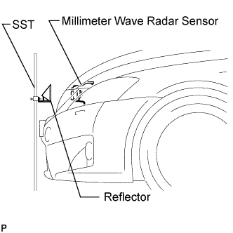
Adjust the reflector height.
-
Adjust the reflector so that the center of the SST reflector is the same height as the millimeter wave radar sensor.
- SST
- 09870-60000 ( 09870-60010 )
- 09870-60040
Tech Tips
Prepare a 10 m (32.81 ft.) string, a string with a sharp-pointed weight (plumb bob), and a 5 m (16.41 ft.) tape measure.
-
-
Place the reflector.
-
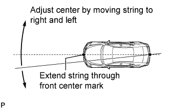
Hang the string (with a weight) from the center of the vehicle rear emblem. Mark the vehicle rear center point on the ground. Repeat the same procedure for the front of the vehicle.
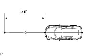
-
Set one end of the 10 m (32.82 ft.) string on the vehicle rear center point. Run the string over the vehicle front center point to a position 5 m (16.41 ft.) beyond the vehicle front center point, as shown in the illustration. Mark the 5 m (16.41 ft.) position.
-
Using the tape measure, measure 12 mm (0.47 in.) to the left of the 5 m (16.41 ft.) position. Place the reflector at that position.
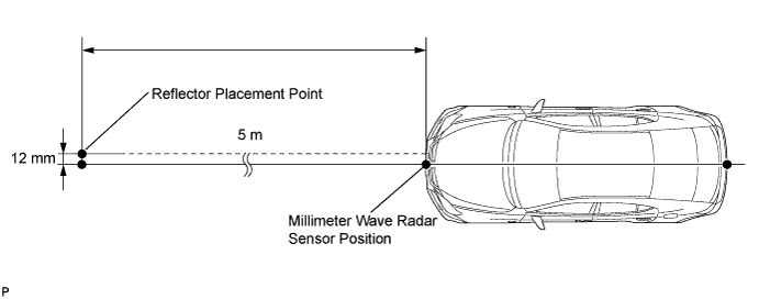
Note
Perform the operation as precisely as possible.
-
-
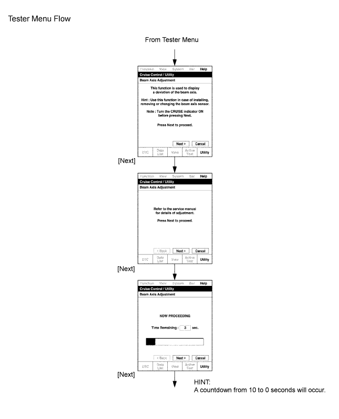
Adjust the radar beam axis.
-
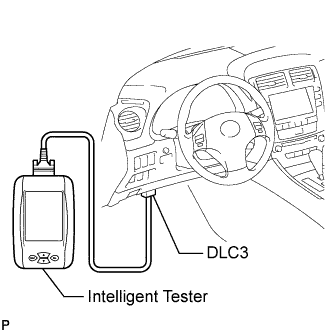
Connect the intelligent tester to the DLC3.
-
Turn the engine switch on (IG).
-
Turn the intelligent tester main switch on, and turn the cruise control main switch on.
Tech Tips
If an error message is displayed on the screen, initialization of the distance control ECU may not be completed. Initialize the distance control ECU Click here.
-
-
Check and adjust the horizontal direction of the radar sensor.
-
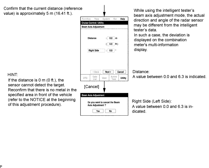
Check that the divergence of the radar beam axis is 0° .
Standard 0° (Both right and left) If the divergence is not as specified, use a screwdriver to adjust bolt B until the divergence of the radar beam axis is 0°. -
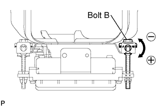
Based on the measured divergence of the beam axis, turn and adjust bolt B for horizontal adjustment of the millimeter wave radar sensor using a screwdriver.
Result Adjustment Direction Adjustment Procedure Adjustment Angle Horizontal adjustment
-
Right direction: Turn bolt B to positive (+) side
-
Left direction: Turn bolt B to negative (-) side
For every 18.6 rotations of adjustment bolt, sensor moves about 1° Tech Tips
-
If "LEFT SIDE: 1.0°" is displayed, the divergence is 1.0° to the left . Turn bolt B approximately 3 turns to the negative (-) side.
-
If the value does not change to 0°, it is possible that the sensor is aiming at something different. Reconfirm that there are no reflective materials in the surrounding area.
-
-
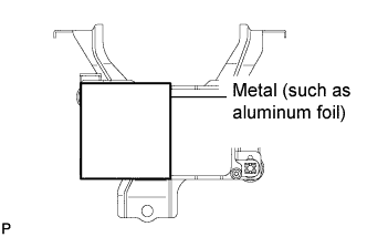
Reset the radar sensor's driving learning values. Prepare a piece of metal that can block radio waves, such as aluminum foil. Cover the radar sensor's right half with the aluminum foil for 10 seconds.
Note
Be sure to keep the reflector in place and make sure that there is nothing between the sensor's left half and the reflector.
Tech Tips
When the reset is completed, the buzzer sounds for 10 seconds.
-
Disconnect the intelligent tester from the DLC3.
-
-
Recheck and readjust the vertical direction of the radar sensor.
-
Set a level on the radar sensor's level rack.
-
Check that the air bubble is within the red frame on the level.
OK The air bubble is within the red frame on the level. If the bubble is not within the red frame, use a screwdriver to adjust bolt A until the air bubble is within the red frame. Tech Tips
-
The adjustable range within the red frame on the level is +/- 0.2°.
-
The target angle is +0.2° (upward angle of 0.2°).
Result Adjustment Direction Adjustment Procedure Adjustment Angle Vertical adjustment
-
Left direction: Turn bolt A to negative (-) side
-
Right direction: Turn bolt A to positive (+) side
For every 8.4 rotations of adjustment bolt, sensor moves about 1° -
-
-
-
VEHICLE PREPARATION FOR FOG LIGHT AIMING
-
Prepare the vehicle:
-
Ensure that that there is no damage or deformation to the body around the fog lights.
-
Fill the fuel tank.
-
Make sure that the oil is filled to the specified level.
-
Make sure that the engine coolant is filled to the specified level.
-
Inflate the tires to the appropriate pressure.
-
Unload the trunk and vehicle, ensuring that the spare tire, tools, and jack are in their original positions.
-
Sit a person of average weight (75 kg, 165 lb) in the driver's seat.
-
Vehicles with height adjustable suspension should set the vehicle height to the lowest setting prior to adjusting the fog light aim.
-
-
-
PREPARATION FOR FOG LIGHT AIMING
-

Prepare the vehicle:
-
Place the vehicle in a location that is dark enough to clearly observe the cutoff line. The cutoff line is a distinct line, below which light from the fog lights can be observed and above which it cannot.
-
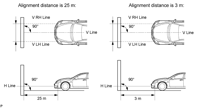
Place the vehicle at a 90° angle to the wall.
-
Create a 25 m (82 ft.) distance between the vehicle (fog light bulb center) and the wall.
-
Make sure that the vehicle is on a level surface.
-
Position the front wheels straight ahead.
-
Bounce the vehicle up and down several times to settle the suspension.
Note
A distance of 25 m (82 ft.) between the vehicle (fog light bulb center) and the wall is necessary for proper aim adjustment. If sufficient space is not available, secure a distance of exactly 3 m (9.84 ft.) to allow for checking and adjustment of fog light aim. (The size of the target zone will change with the distance, so follow the instructions in the illustration.)
-
-
Prepare a piece of thick white paper (approximately 2 m (6.6 ft.) (height) x 4 m (13.1 ft.) (width)) to use as a screen.
-
Draw a vertical line down the center of the screen (V line).
-
Set the screen as shown in the illustration.
Tech Tips
-
Stand the screen perpendicular to the ground.
-
Align the V line on the screen with the center of the vehicle.
-
-
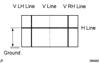
Draw base lines (H, V LH, and V RH lines) on the screen as shown in the illustration.
Tech Tips
Mark the fog light bulb center marks on the screen. If the center mark cannot be observed on the fog light, use the center of the fog light bulb or the manufacturer's name marked on the fog light as the center mark.
-
H Line (Fog light height):
Draw a horizontal line across the screen so that it passes through the center marks. The H line should be at the same height as the fog light bulb center marks of the fog lights.
-
V LH Line, V RH Line (Center mark positions of left-hand (LH) and right-hand (RH) fog lights):
Draw two vertical lines so that they intersect the H line at each center mark aligned with the center of the fog light bulbs.
-
-
-
INSPECT FOG LIGHT AIMING
-
Cover the fog light or disconnect the connector of the fog light on the opposite side to prevent light from the fog light that is not being inspected from affecting the fog light aiming inspection.
Note
Do not keep the fog light covered for more than 3 minutes. The fog light lens is made of synthetic resin, which may melt or be damaged due to excessive heat.
-
Start the engine.
-
Turn on the fog light and check if the cutoff line falls within the specified area in the following illustration.
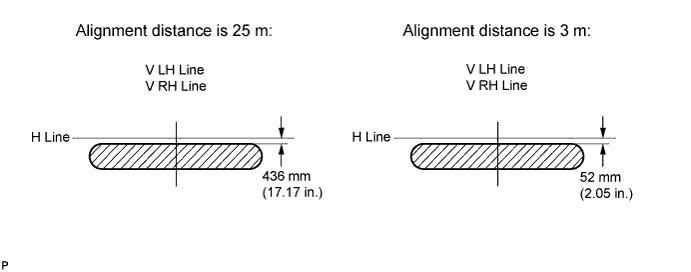
-
-
ADJUST FOG LIGHT AIMING
-
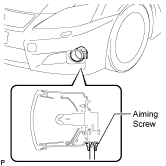
Adjust the aim vertically:
Adjust the aim of each fog light to the specified range by turning each aiming screw with a screwdriver.
Note
The final turn of the aiming screw should be made in the clockwise direction. If the screw is tightened excessively, loosen it and then retighten it so that the final turn of the screw is in the clockwise direction.
Tech Tips
If it is not possible to correctly adjust the fog light aim, check bulb, fog light unit, and fog light unit reflector installation.
-