COOLING FAN SYSTEM Cooling Fan Circuit
DESCRIPTION
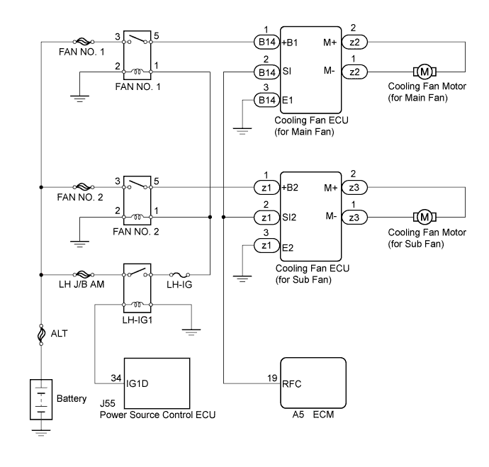
The ECM calculates an appropriate cooling fan speed based on the engine coolant temperature, air conditioning switch condition, refrigerant pressure, engine speed, and vehicle speed and sends the signals to the cooling fan ECUs to regulate the cooling fans. The cooling fan ECUs control each cooling fan speed based on the duty ratio signal sent from the ECM. By basing its control on the operating conditions, the ECM can control the fan speed optimally using the cooling fan ECUs, achieving both high cooling performance and quietness. The cooling fan speed is determined based on engine coolant temperature, air conditioner operating conditions, engine speed, and vehicle speed.
WIRING DIAGRAM
INSPECTION PROCEDURE
PROCEDURE
-
PERFORM ACTIVE TEST USING INTELLIGENT TESTER (CONTROL THE COOLING FAN)
-
Connect the intelligent tester to the DLC3.
-
Turn the engine switch on (IG).
-
Enter the following menus: Powertrain / Engine / Active Test / Control the Cooling Fan.
-
Check the operation of the cooling fan while operating it using the intelligent tester.
OK Tester Operation Fan Operation ON Cooling fan rotates OFF Cooling fan stopped Result Result Proceed to OK A NG (Main fan) B NG (Sub fan) C NG (Main and sub fans) D
B 
INSPECT COOLING FAN SYSTEM (FOR MAIN FAN) Click here
C
INSPECT COOLING FAN SYSTEM (FOR SUB FAN) Click here
D
INSPECT COOLING FAN SYSTEM Click here
A 
REPLACE ECM Click here
-
-
INSPECT COOLING FAN SYSTEM (FOR MAIN FAN)
-
Disconnect the ECM connector.
-
Turn the engine switch on (IG).
-
Check the operation of the cooling fan.
OK The cooling fan rotates.
NG
CHECK HARNESS AND CONNECTOR (ECM - COOLING FAN ECU (FOR MAIN FAN)) Click here
OK 
-
-
CHECK HARNESS AND CONNECTOR (ECM - COOLING FAN ECU (FOR MAIN FAN))
-
Disconnect the cooling fan ECU connector.
-
Disconnect the ECM connector.
-
Measure the resistance according to the value(s) in the table below.
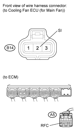
Standard Resistance Tester Connection Condition Specified Condition A5-19 (RFC) - B14-2 (SI) Always Below 1 Ω
NG 
REPAIR OR REPLACE HARNESS OR CONNECTOR
OK
REPLACE COOLING FAN ECU (FOR MAIN FAN)
-
-
CHECK HARNESS AND CONNECTOR (ECM - COOLING FAN ECU (FOR MAIN FAN))
-
Disconnect the cooling fan ECU connector.
-
Disconnect the ECM connector.
-
Measure the resistance according to the value(s) in the table below.
Standard Resistance Tester Connection Condition Specified Condition A5-19 (RFC) or B14-2 (SI) - Body ground Always 10 kΩ or higher
NG
REPAIR OR REPLACE HARNESS OR CONNECTOR
OK
-
-
INSPECT COOLING FAN MOTOR (FOR MAIN FAN)
-
Inspect the cooling fan motor Click here.
NG
REPLACE COOLING FAN MOTOR (FOR MAIN FAN) Click here
OK
-
-
CHECK ECU POWER SOURCE CIRCUIT (FOR MAIN FAN)
-
Disconnect the cooling fan ECU connector.
-
Turn the engine switch on (IG).
-
Measure the voltage according to the value(s) in the table below.
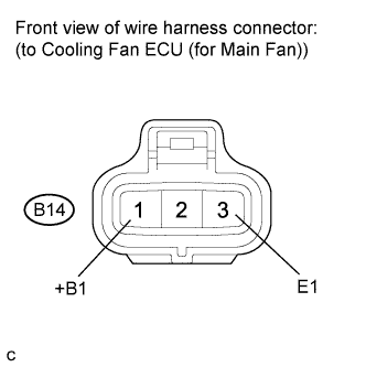
Standard Voltage Tester Connection Switch Condition Specified Condition B14-1 (+B1) - B14-3 (E1) Engine switch on (IG) 11 to 14 V
NG
CHECK HARNESS AND CONNECTOR (COOLING FAN ECU (FOR MAIN FAN) - BODY GROUND) Click here
OK
REPLACE COOLING FAN ECU (FOR MAIN FAN)
-
-
CHECK HARNESS AND CONNECTOR (COOLING FAN ECU (FOR MAIN FAN) - BODY GROUND)
-
Measure the resistance according to the value(s) in the table below.
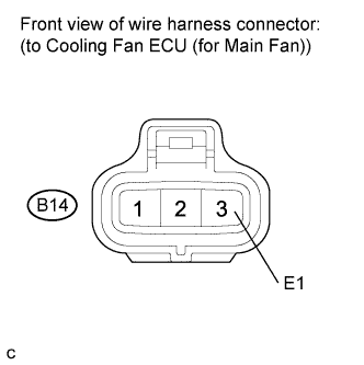
Standard Resistance Tester Connection Condition Specified Condition B14-3 (E1) - Body ground Always Below 1 Ω
NG
REPAIR OR REPLACE HARNESS OR CONNECTOR
OK
-
-
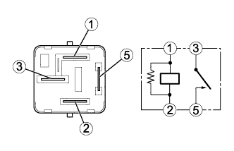
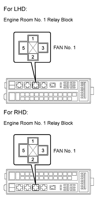
INSPECT FAN NO. 1 RELAY
-
Remove the FAN No. 1 relay from the engine room No. 1 relay block.
-
Measure the resistance according to the value(s) in the table below.
Standard Resistance Tester Connection Condition Specified Condition 3 - 5 Normal 10 kΩ or higher 3 - 5 Battery voltage applied between terminals 1 and 2 Below 1 Ω
NG
REPLACE FAN NO. 1 RELAY
OK
-
-
CHECK HARNESS AND CONNECTOR (FAN NO. 1 RELAY - BATTERY)
-
Remove the FAN No. 1 relay from the engine room No. 1 relay block.
-
Measure the voltage according to the value(s) in the table below.
Standard Voltage Tester Connection Condition Specified Condition 3 (FAN No.1 relay) - Body ground Always 11 to 14 V
NG
INSPECT FUSIBLE LINK BLOCK (FAN NO. 1 FUSE) Click here
OK
-
-
CHECK HARNESS AND CONNECTOR (FAN NO. 1 RELAY - LH-IG FUSE)
-
Remove the FAN No. 1 relay from the engine room No. 1 relay block.
-
Measure the voltage according to the value(s) in the table below.
Standard Voltage Tester Connection Condition Specified Condition 1 (FAN No.1 relay) - Body ground Always 11 to 14 V
NG
REPAIR OR REPLACE HARNESS OR CONNECTOR
OK
-
-
CHECK HARNESS AND CONNECTOR (FAN NO. 1 RELAY - BODY GROUND)
-
Remove the FAN No. 1 relay from the engine room No. 1 relay block.
-
Measure the resistance according to the value(s) in the table below.
Standard Resistance Tester Connection Condition Specified Condition 2 (FAN No.1 relay) - Body ground Always Below 1 Ω
NG
REPAIR OR REPLACE HARNESS OR CONNECTOR (FAN NO. 1 RELAY - BODY GROUND)
OK
REPAIR OR REPLACE HARNESS OR CONNECTOR (COOLING FAN ECU (FOR MAIN FAN) - FAN NO. 1 RELAY)
-
-
INSPECT FUSIBLE LINK BLOCK (FAN NO. 1 FUSE)
-
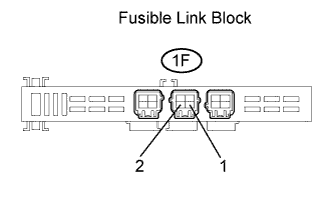
Remove the fusible link block from the engine room No. 1 relay block.
-
Measure the resistance according to the value(s) in the table below.
Standard Resistance Tester Connection Condition Specified Condition 1F-1 - 1F-2 Always Below 1 Ω
NG
REPLACE FUSIBLE LINK BLOCK
OK
REPAIR OR REPLACE HARNESS OR CONNECTOR (FAN NO. 1 RELAY - BATTERY)
-
-
INSPECT COOLING FAN SYSTEM (FOR SUB FAN)
-
Disconnect the ECM connector.
-
Turn the engine switch on (IG).
-
Check the operation of the cooling fan.
OK The cooling fan rotates.
NG
CHECK HARNESS AND CONNECTOR (COOLING FAN ECU (FOR SUB FAN) - ECM) Click here
OK
-
-
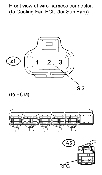
CHECK HARNESS AND CONNECTOR (COOLING FAN ECU (FOR SUB FAN) - ECM)
-

Disconnect the cooling fan ECU connector.
-
Disconnect the ECM connector.
-
Measure the resistance according to the value(s) in the table below.
Standard Resistance Tester Connection Condition Specified Condition A5-19 (RFC) - z1-2 (SI2) Always Below 1 Ω
NG
REPAIR OR REPLACE HARNESS OR CONNECTOR
OK
REPLACE ECM Click here
-
-
CHECK HARNESS AND CONNECTOR (COOLING FAN ECU (FOR SUB FAN) - ECM)
-
Disconnect the cooling fan ECU connector.
-
Disconnect the ECM connector.
-
Measure the resistance according to the value(s) in the table below.
Standard Resistance Tester Connection Condition Specified Condition A5-19 (RFC) or z1-2 (SI2) - Body ground Always 10 kΩ or higher
NG
REPAIR OR REPLACE HARNESS OR CONNECTOR
OK
-
-
INSPECT COOLING FAN MOTOR (FOR SUB FAN)
-
Inspect the cooling fan motor Click here.
NG
REPLACE COOLING FAN MOTOR (FOR SUB FAN) Click here
OK
-
-
CHECK ECU POWER SOURCE CIRCUIT (FOR SUB FAN)
-
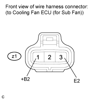
Disconnect the cooling fan ECU connector.
-
Turn the engine switch on (IG).
-
Measure the voltage according to the value(s) in the table below.
Standard Voltage Tester Connection Switch Condition Specified Condition z1-1 (+B2) - z1-3 (E2) Engine switch on (IG) 11 to 14 V
NG
CHECK HARNESS AND CONNECTOR (COOLING FAN ECU (FOR SUB FAN) - BODY GROUND) Click here
OK
REPLACE COOLING FAN ECU (FOR SUB FAN)
-
-
CHECK HARNESS AND CONNECTOR (COOLING FAN ECU (FOR SUB FAN) - BODY GROUND)
-
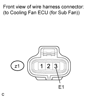
Measure the resistance according to the value(s) in the table below.
Standard Resistance Tester Connection Condition Specified Condition z1-3 (E2) - Body ground Always Below 1 Ω
NG
REPAIR OR REPLACE HARNESS OR CONNECTOR
OK
-
-
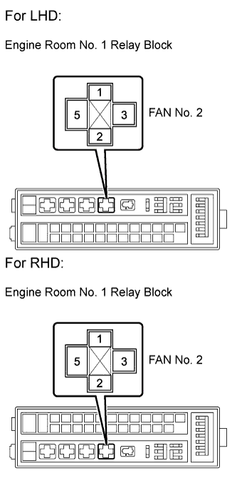
INSPECT FAN NO. 2 RELAY
-
Remove the FAN No. 2 relay from the engine room No. 1 relay block.
-
Measure the resistance according to the value(s) in the table below.
Standard Resistance Tester Connection Condition Specified Condition 3 - 5 Normal 10 kΩ or higher 3 - 5 Battery voltage applied between terminals 1 and 2 Below 1 Ω
NG
REPLACE FAN NO. 2 RELAY
OK
-
-
CHECK HARNESS AND CONNECTOR (FAN NO. 2 RELAY - BATTERY)
-
Remove the FAN No. 2 relay from the engine room No. 1 relay block.
-
Measure the voltage according to the value(s) in the table below.
Standard Voltage Tester Connection Condition Specified Condition 3 (FAN No. 2 relay) - Body ground Always 11 to 14 V
NG
INSPECT FUSIBLE LINK BLOCK (FAN NO. 2 FUSE) Click here
OK
-
-
CHECK HARNESS AND CONNECTOR (FAN NO. 2 RELAY - LH-IG FUSE)
-
Remove the FAN No. 2 relay from the engine room No. 1 relay block.
-
Measure the voltage according to the value(s) in the table below.
Standard Voltage Tester Connection Condition Specified Condition 1 (FAN No. 2 relay) - Body ground Always 11 to 14 V
NG
REPAIR OR REPLACE HARNESS OR CONNECTOR
OK
-
-
CHECK HARNESS AND CONNECTOR (FAN NO. 2 RELAY - BODY GROUND)
-
Remove the FAN No. 2 relay from the engine room No. 1 relay block.
-
Measure the resistance according to the value(s) in the table below.
Standard Resistance Tester Connection Condition Specified Condition 2 (FAN No. 2 relay) - Body ground Always Below 1 Ω
NG
REPAIR OR REPLACE HARNESS OR CONNECTOR (FAN NO. 2 RELAY - BODY GROUND)
OK
REPAIR OR REPLACE HARNESS OR CONNECTOR (COOLING FAN ECU (FOR SUB FAN) - FAN NO. 2 RELAY)
-
-
INSPECT FUSIBLE LINK BLOCK (FAN NO. 2 FUSE)
-
Remove the fusible link block from the engine room No. 1 relay block.
-
Measure the resistance according to the value(s) in the table below.
Standard Resistance Tester Connection Condition Specified Condition FAN No. 2 fuse Always Below 1 Ω
NG
REPLACE FUSIBLE LINK BLOCK
OK
REPAIR OR REPLACE HARNESS OR CONNECTOR (FAN NO. 2 RELAY - BATTERY)
-
-
INSPECT COOLING FAN SYSTEM
-
Disconnect the ECM connector.
-
Turn the engine switch on (IG).
-
Check the operation of the cooling fan.
OK The cooling fan rotates.
NG
CHECK HARNESS AND CONNECTOR (ECM - COOLING FAN ECU (FOR MAIN AND SUB FAN)) Click here
OK
-
-
CHECK HARNESS AND CONNECTOR (ECM - COOLING FAN ECU (FOR MAIN AND SUB FAN))
-
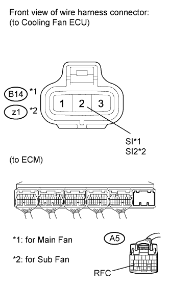
Disconnect the cooling fan ECU connector.
-
Disconnect the ECM connector.
-
Measure the resistance according to the value(s) in the table below.
Standard Resistance Tester Connection Condition Specified Condition A5-19 (RFC) - B14-2 (SI) Always Below 1 Ω A5-19 (RFC) - z1-2 (SI2) Always Below 1 Ω
NG
REPAIR OR REPLACE HARNESS OR CONNECTOR
OK
REPLACE ECM Click here
-
-
CHECK HARNESS AND CONNECTOR (ECM - COOLING FAN ECU (FOR MAIN AND SUB FAN))
-

Disconnect the cooling fan ECU connector.
-
Disconnect the ECM connector.
-
Measure the resistance according to the value(s) in the table below.
Standard Resistance Tester Connection Condition Specified Condition A5-19 (RFC), B14-2 (SI) or z1-2 (SI2) - Body ground Always 10 kΩ or higher
NG
REPAIR OR REPLACE HARNESS OR CONNECTOR
OK
-
-
INSPECT FUSE (LH-IG FUSE)
-
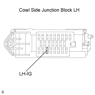
Remove the LH-IG fuse from the cowl side junction block LH.
-
Measure the resistance according to the value(s) in the table below.
Standard Resistance Tester Connection Condition Specified Condition LH-IG fuse Always Below 1 Ω
NG
REPLACE FUSE (LH-IG FUSE)
OK
-
-
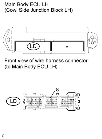
INSPECT MAIN BODY ECU LH (IG1 RELAY)
-
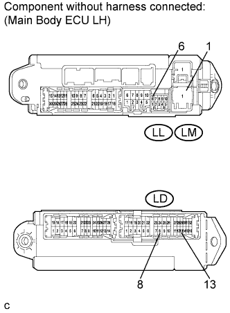
Disconnect the main body ECU LH (cowl side junction block LH) connectors.
-
Measure the resistance according to the value(s) in the table below.
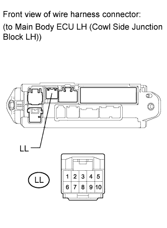
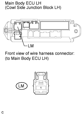
Standard Resistance Tester Connection Condition Specified Condition LL-6 - LM-1 Normal 10 kΩ or higher LL-6 - LM-1 Battery voltage applied between terminals LD-8 and LD-13 Below 1 Ω
NG
REPLACE MAIN BODY ECU LH (COWL SIDE JUNCTION BLOCK LH)
OK
-
-
CHECK HARNESS AND CONNECTOR (IG1 RELAY - FAN NO. 1 RELAY)
-
Remove the FAN No. 1 relay from the engine room No. 1 relay block.
-
Disconnect the main body ECU LH (cowl side junction block LH) connector.
-
Measure the resistance according to the value(s) in the table below.
Standard Resistance Tester Connection Condition Specified Condition LL-6 - 1 (FAN No. 1 relay) Always Below 1 Ω
NG
REPAIR OR REPLACE HARNESS OR CONNECTOR
OK
-
-
CHECK HARNESS AND CONNECTOR (IG1 RELAY POWER SOURCE)
-
Disconnect the main body ECU (cowl side junction block LH) connector.
-
Measure the voltage according to the value(s) in the table below.
Standard Voltage Tester Connection Switch Condition Specified Condition LM-1 - Body ground Engine switch on (IG) 11 to 14 V
NG
CHECK HARNESS AND CONNECTOR (MAIN BODY ECU LH - POWER SOURCE CONTROL ECU) Click here
OK
-
-
CHECK HARNESS AND CONNECTOR (MAIN BODY ECU LH - BODY GROUND)
-
Disconnect the main body ECU LH (cowl side junction block LH) connector.
-
Measure the resistance according to the value(s) in the table below.
Standard Resistance Tester Connection Condition Specified Condition LD-8 - Body ground Always Below 1 Ω
NG
REPAIR OR REPLACE HARNESS OR CONNECTOR (MAIN BODY ECU LH - BODY GROUND)
OK
REPAIR OR REPLACE HARNESS OR CONNECTOR (BATTERY - MAIN BODY ECU LH)
-
-
CHECK HARNESS AND CONNECTOR (MAIN BODY ECU LH - POWER SOURCE CONTROL ECU)
-
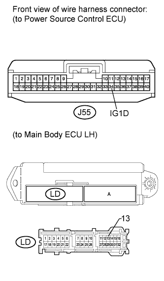
Disconnect the main body ECU LH (cowl side junction block LH) connector.
-
Disconnect the power source control ECU connector.
-
Measure the resistance according to the value(s) in the table below.
Standard Resistance Tester Connection Condition Specified Condition J55-34 (IG1D) - LD-13 (Main body ECU LH) Always Below 1 Ω
NG
REPAIR OR REPLACE HARNESS OR CONNECTOR
OK
GO TO ENTRY AND START SYSTEM Click here
-