COOLING FAN SYSTEM ON-VEHICLE INSPECTION

-
CHECK COOLING FAN SYSTEM
-
Check the operation of the cooling fan.
-
Connect the intelligent tester to the DLC3.
-
Turn the engine switch on (IG).
-
Enter the following menus: Powertrain / Engine / Active Test / Control the Electric Cooling Fan.
-
Check the operation of the cooling fan while operating it using the intelligent tester.
If the cooling fan motor does not operate, check the cooling fan circuit Click here.
-
-
Check the input signal and output current.
Tech Tips
Be sure to perform the inspection with the engine coolant temperature less than 92°C (198°F).
-
Connect the 400 A probe of an ammeter to the cooling fan motor (M+), and then to the No. 2 cooling fan motor (S+) on the wire harness side.
-
Using an oscilloscope, check the waveform between terminals A5-19 (RFC) and E6-1 (E1) of the ECM.
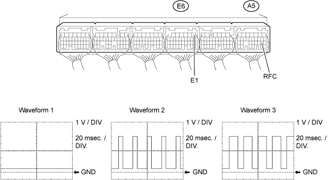
Standard Waveform Condition Input Signal Output Current Engine stopped
(engine switch on (IG))
Waveform 1
(Duty ratio 0%)
(Fan stops) Engine idling
(A/C OFF)
Waveform 1
(Duty ratio 0%)
(Fan stops) Engine idling
(A/C ON)
Waveform 2
(Duty ratio 50 to 70%)
2 to 22 A for cooling fan motor
2 to 22 A for No. 2 cooling fan motor
(Fan operates)
Engine idling
(engine coolant temperature sensor connector disconnected)
Waveform 3
(Duty ratio 50 to 70%)
2 to 22 A for cooling fan motor
2 to 22 A for No. 2 cooling fan motor
(Fan operates)
-
If the input signal is abnormal, there is a malfunction in the ECM or cooling fan ECU.
-
If the output current is abnormal even when the input signal is normal, there is a malfunction in the cooling fan ECU or cooling fan motor Click here.
-
-
-