INTAKE MANIFOLD REMOVAL

-
DISCONNECT CABLE FROM NEGATIVE BATTERY TERMINAL
CAUTION:
Wait at least 90 seconds after disconnecting the cable from the negative (-) battery terminal to disable the SRS system.
Note
When disconnecting the cable, some systems need to be initialized after the cable is reconnected Click here.
-
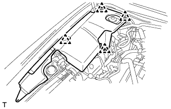
REMOVE V-BANK COVER SUB-ASSEMBLY
-
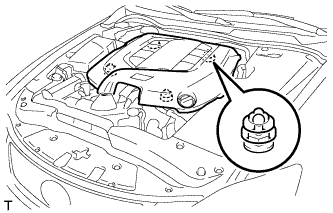
Hold the front of the V-bank cover sub-assembly and raise it to disengage the 2 clips on the front of the cover. Continue to raise the cover to disengage the 2 clips on the rear of the cover and remove the V-bank cover sub-assembly.
Note
Attempting to disengage both front and rear clips at the same time may cause the cover to break.
-
-
REMOVE COOL AIR INTAKE DUCT SEAL
-
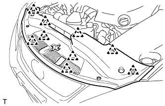
Remove the 9 clips and cool air intake duct seal.
-
-
REMOVE ENGINE ROOM SIDE COVER LH (for LHD)
-

Remove the 5 clips and engine room side cover LH.
-
-
REMOVE ENGINE ROOM SIDE COVER LH (for RHD)
-
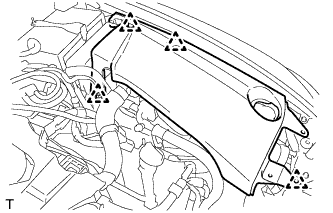
Remove the 4 clips and engine room side cover LH.
-
-
REMOVE ENGINE ROOM SIDE COVER RH (for LHD)
-
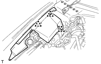
Remove the 3 clips and engine room side cover RH.
-
-
REMOVE ENGINE ROOM SIDE COVER RH (for RHD)
-
Remove the 4 clips and engine room side cover RH.
-
-
REMOVE NO. 1 AIR CLEANER INLET
-
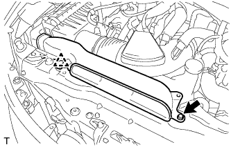
Remove the bolt, clip and No. 1 air cleaner inlet.
-
-
REMOVE AIR CLEANER CAP SUB-ASSEMBLY
-
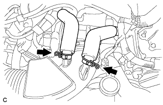
Loosen the 2 hose clamps and separate the 2 ventilation hoses.
-
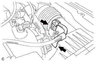
Disconnect the mass air flow meter connector and separate the wire harness clamp.
-
Loosen the hose clamp and separate the air cleaner hose.
-
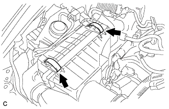
Unlock the 2 clamps and remove the air cleaner cap sub-assembly.
-
-
REMOVE AIR CLEANER CASE SUB-ASSEMBLY
-
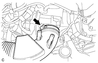
Remove the 2 clamps and disconnect the vacuum hose.
-
Remove the clamp and disconnect the vacuum switching valve connector.
-
Remove the 2 bolts and air cleaner case sub-assembly.
-
-
REMOVE NO. 1 ENGINE ROOM RELAY BLOCK COVER (for LHD)
-
Remove the No. 1 engine room relay block cover.
-
-
REMOVE ENGINE UNDER COVER
-
REMOVE REAR ENGINE UNDER COVER RH
-
REMOVE NO. 2 ENGINE UNDER COVER
-
DRAIN ENGINE COOLANT
-
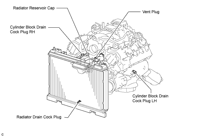
Loosen the radiator drain cock plug.
CAUTION:
Do not loosen the radiator drain cock plug while the engine and radiator are still hot. Pressurized, hot engine coolant and steam may be released and cause serious burns.
Tech Tips
Collect the coolant in a container and dispose of it according to local regulations.
-
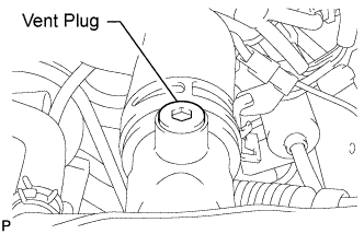
Remove the radiator reservoir cap, and using a 6 mm socket hexagon wrench, remove the vent plug.
-
Drain coolant.
-
Loosen the 2 cylinder block drain cock plugs.
-
-
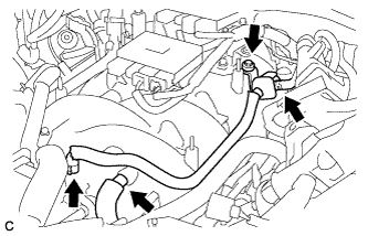
REMOVE THROTTLE BODY ASSEMBLY
-
Disconnect the throttle body assembly connector.
-
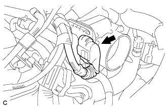
Loosen the hose clamp and separate the No. 5 water by-pass hose.
-
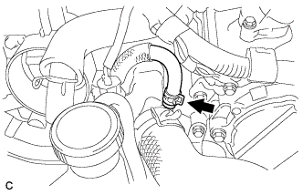
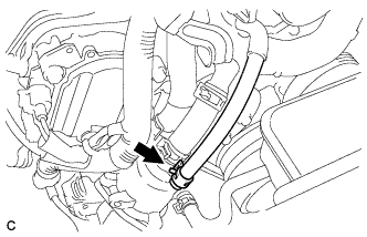
Loosen the hose clamp and separate the No. 4 water by-pass hose.
-
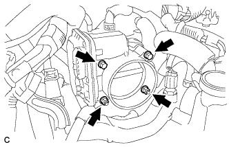
Remove the 2 bolts and 2 nuts.
-
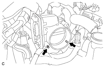
Using a "TORX" socket E6, remove the 2 stud bolts and throttle body assembly.
Note
Do not damage the water hoses when removing the throttle body assembly.
-
Remove the gasket.
-
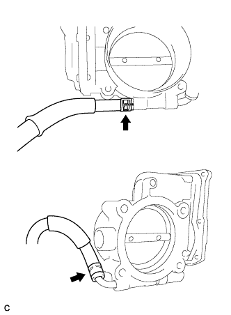
Remove the 2 water by-pass hoses from the throttle body assembly.
-
-
SEPARATE OIL COOLER TUBE SUB-ASSEMBLY
-
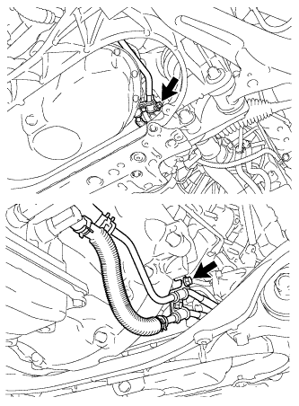
Remove the 2 bolts and separate the oil cooler tube sub-assembly.
-
-
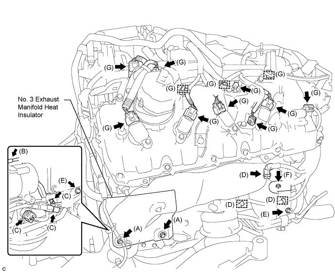
DISCONNECT ENGINE WIRE (for LHD)
Tech Tips
Secure disconnected harnesses, etc. with tape or equivalent so that they do not interfere.
-
Disconnect the engine wire.
-
Remove the 2 bolts from the No. 3 exhaust manifold heat insulator. (A)
-
Disconnect the starter connector. (B)
-
Disconnect the 2 connectors and then remove the nut. (C)
-
Disconnect the generator connector and 2 clamps. (D)
-
Remove the bolt, nut and separate the oil cooler tube sub-assembly. (E)
-
Remove the nut and disconnect the harness from the +B terminal. (F)
-
Disconnect the 9 connectors and 3 clamps. (G)
-
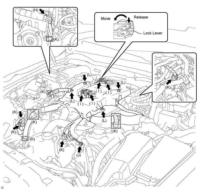
Remove the nut and disconnect the wire harness from the relay box. (H)
-
Disconnect the 4 injector driver connectors. (I)
Tech Tips
To disconnect the injector driver connectors, push the claw downward and move the lock lever to release the lock.
-
Remove the bolt and ground cable. (J)
-
Disconnect the 4 connectors and 5 clamps. (K)
-
Remove the 4 nuts and disconnect the engine wire. (L)
-
-
-
DISCONNECT ENGINE WIRE (for RHD)
Tech Tips
Secure disconnected harnesses, etc. with tape or equivalent so that they do not interfere.
-
Disconnect the engine wire.
-
Remove the 2 bolts from the No. 3 exhaust manifold heat insulator. (A)
-
Disconnect the starter connector. (B)
-
Disconnect the 2 connectors and then remove the nut. (C)
-
Disconnect the generator connector and 2 clamps. (D)
-
Remove the bolt, nut and separate the oil cooler tube sub-assembly. (E)
-
Remove the nut and disconnect the harness from the +B terminal. (F)
-
Disconnect the 9 connectors and 3 clamps. (G)
-
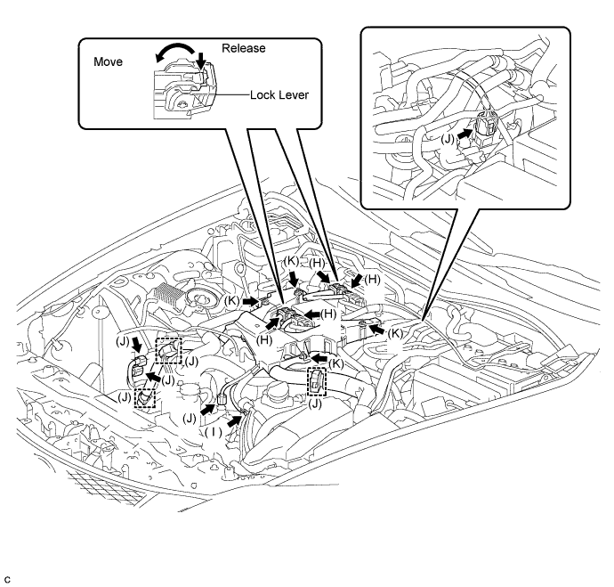
Disconnect the 4 injector driver connectors. (H)
Tech Tips
To disconnect the injector driver connectors, push the claw downward and move the lock lever to release the lock.
-
Remove the bolt and ground cable. (I)
-
Disconnect the 4 connectors and 3 clamps. (J)
-
Remove the 4 nuts and disconnect the engine wire. (K)
-
-
-
REMOVE NO. 1 VACUUM SWITCHING VALVE ASSEMBLY
-
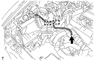
Disconnect the fuel vapor feed hose from the intake air surge tank assembly.
-
Remove the No. 2 fuel vapor feed hose from the No. 1 vacuum switching valve assembly.
-
Remove the bolt and No. 1 vacuum switching valve assembly.
-
Disconnect the ventilation hose.
-
-
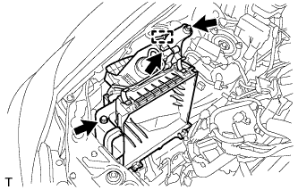
REMOVE INJECTOR DRIVER
-
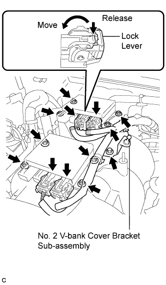
Disconnect the 4 injector driver connectors.
Tech Tips
To disconnect the injector driver connectors, push the claw downward and move the lock lever to release the lock.
-
Remove the 8 nuts and 2 injector drivers.
-
Remove the bolt and No. 2 V-bank cover bracket sub-assembly.
-
-
REMOVE WATER BY-PASS PIPE SUB-ASSEMBLY
-
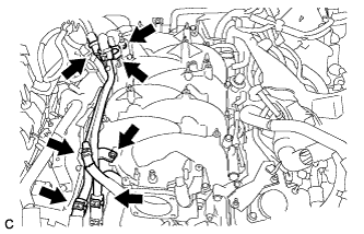
Slide the 5 clamps, and disconnect the heater inlet water hose, heater outlet water hose, water inlet hose, water outlet hose , and water by-pass hose from the water by-pass pipe sub-assembly.
-
Remove the 2 bolts and water by-pass pipe.
-
-
DISCONNECT VACUUM HOSE ASSEMBLY (for LHD)
-
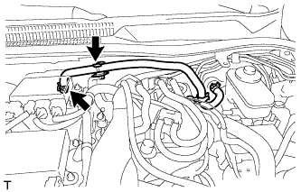
Disconnect the vacuum hose assembly from the hose clamp.
-
Disconnect the vacuum hose assembly from the intake air surge tank assembly.
-
-
DISCONNECT VACUUM HOSE ASSEMBLY (for RHD)
-
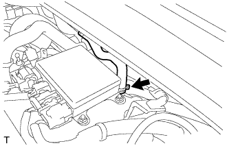
Disconnect the vacuum hose assembly from the intake air surge tank assembly.
-
-
DISCONNECT NO. 3 FUEL HOSE
-
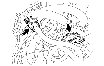
Remove the 2 fuel pipe clamps.
-
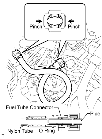
Pinch the fuel tube connector and then pull out the No. 3 fuel hose.
Note
-
Check for any dirt and foreign matter contamination in the pipe and around the connector. Clean if necessary. Foreign matter may damage the O-rings or cause leaks in the seal between the pipe and connector.
-
Do not use any tools to separate the pipe and connector.
-
Do not forcefully bend or twist the nylon tube.
-
Check for any dirt and foreign matter on the pipe seal surface. Clean if necessary.
-
Put the pipe and connector ends in plastic bags to prevent damage and dirt contamination.
-
If the pipe and connector are stuck together, pinch the tube between your fingers and turn it carefully to free it. Then disconnect the hose.
-
-
-
REMOVE FUEL DELIVERY PIPE SUB-ASSEMBLY
-
Disconnect the 8 injector connectors.
-
Remove the 4 bolts and 2 wire harnesses.
-
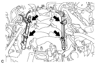
Remove the 4 bolts and fuel delivery pipe sub-assembly and 4 spacers.
-
-
REMOVE INTAKE AIR SURGE TANK ASSEMBLY
-
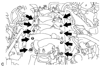
Remove the 8 bolts, 2 nuts and intake air surge tank assembly.
-
Remove the 2 gaskets from the intake air surge tank assembly.
-
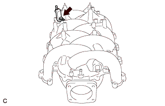
Remove the bolt and V-bank cover bracket sub-assembly.
-
Remove the bolt and union to check valve hose bracket (for LHD).
-